Plug

a technology of plugs and wires, applied in the field of plugs, can solve the problems of increasing data amount, chaos, interference, etc., and achieve the effect of lessening the twisting and winding of wires and keeping the assembling space neat and tidy

Inactive Publication Date: 2006-05-04
MOLEX INC
View PDF2 Cites 15 Cited by
  • Summary
  • Abstract
  • Description
  • Claims
  • Application Information

AI Technical Summary

Benefits of technology

[0005] The objective of the present invention is to provide a plug that lessens twist and winding of the wires during connection and then keeps the assembling space neat and tidy. In order to achieve the objective, a plug is disclosed, which matches a corresponding socket. The plug comprises a body, a shell, a plurality of terminals and a plurality of wires. The body contains a first contact surface directing to the corresponding socket, a second contact surface corresponding to the first contact surface and a plurality of terminal channels penetrating from the first contact surface to the second contact surface. The terminal has a connection end that extends from the second contact surface out of the terminal channel and is received by the shell. The wires are connected to the shell on a side thereof and the connection direction is perpendicular to the first contact surface.

Problems solved by technology

However, with the improved computer operation speeds, the data amount involved is increasing constantly, and the relatively unsophisticated parallel ATA interface is beginning to show its limitations.
In the situations of more devices 9, 9′ in a computer system or compact assembling space, the twisted wires will cause a state of chaos and even interference.

Method used


Image

  • Plug
  • Plug
  • Plug

Examples


Embodiment Construction

[0013] While this invention may be susceptible to embodiment in different forms, there is shown in the drawings and will be described herein in detail, a specific embodiment with the understanding that the present disclosure is to be considered an exemplification of the principles of the invention, and is not intended to limit the invention to that as illustrated.

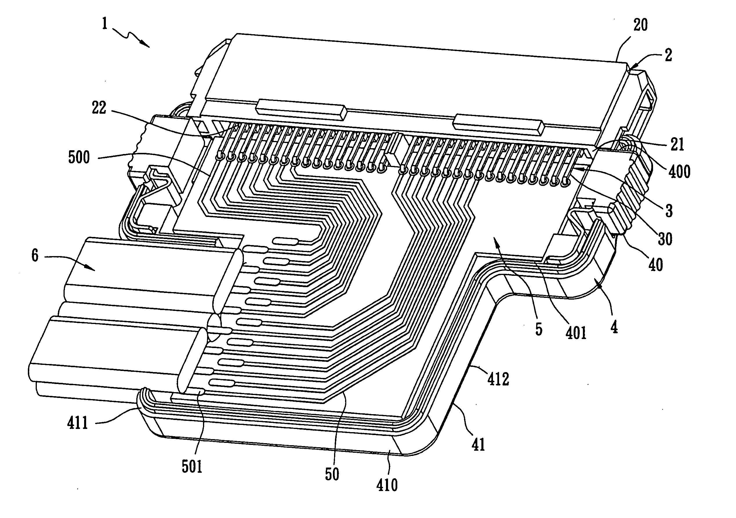
[0014] Referring to FIGS. 3-5 simultaneously, the plug 1, according to a preferred embodiment of the present invention, can match a corresponding socket 7. The plug 1 comprises a body 2, a plurality of terminals 3, a shell 4, a gold finger board 5 and a plurality of wires 6. The body 2, approximately rectangular, contains a first contact surface 20 directing to the socket 7, a second contact surface 21 corresponding the first contact surface 20 and a plurality of terminal channels 22 penetrating from the first contact surface 20 to the second contact surface 21.

[0015] Each terminal 3 has a plug end (not shown) directing t...


PUM


Abstract

The present invention discloses a plug, which matches a corresponding socket. The plug comprises a body, a shell, a plurality of terminals and a plurality of wires. The body has a first contact surface directing to the corresponding socket, a second contact surface corresponding to the first contact surface and a plurality of terminal channels formed between the first contact surface and the second contact surface. Each terminal has a connection end that extends from the second contact surface out of the terminal channel and is accepted by the shell. On one side of the shell, the wires connect to the shell and the connection direction is vertical to the first contact surface. A gold finger board, placed in the shell, has a plurality of leads, each lead having a soldering pad connecting to the corresponding terminal at one end and having a gold finger connecting to the corresponding wire at another end. The plug of present invention provides the advantages of avoiding twisting of the wire and saving space.

Description

FIELD OF THE INVENTION [0001] The present invention relates to a plug, more particularly to a plug wherein the wires of a cable connected to the plug is capable of being connected from a side of the plug shell. BACKGROUND OF THE INVENTION [0002] Since the 1980s, the ATA (Advanced Technology Attachment) interface has been the desktop computer standard for memory storage equipment interconnection. However, with the improved computer operation speeds, the data amount involved is increasing constantly, and the relatively unsophisticated parallel ATA interface is beginning to show its limitations. Therefore, the SATA standard naturally plays an upgrading role. For users, equipment using SATA device(s) will provide the advantages of faster data transmission, high reliability and easier operation. [0003]FIG. 1 is a perspective view of a conventional SATA plug 8. The SATA plug 8 comprises a body 80, a shell 81, a plurality of terminals 82 and a plurality of wires 83 connected to the termina...

Claims


Application Information

Patent Timeline
Patent Type & Authority Applications(United States)
IPC IPC(8): H05K1/00H01R13/66H01R24/06H05K1/11
CPCH01R13/6658H05K1/117H05K2201/09227H05K2201/09709H05K2201/10189
Inventor LI, GUOLI
Owner MOLEX INC
Why Eureka
Try Eureka