
Motorcycle engine and transmission interbracing member

a technology for transmission interbracing and motorcycle engines, which is applied in the direction of jet propulsion mounting, combustion air/fuel air treatment, and bicycle equipment, etc. it can solve the problems of inability to prevent the pivoting of the engine about the horizontal and transverse axis with respect to the motorcycle frame, and the primary drive housing does not provide significant rigidity. , to achieve the effect of reducing torquing, twisting and other problems

Inactive Publication Date: 2005-09-13
THURM KENNETH R +1
View PDF8 Cites 14 Cited by
  • Summary
  • Abstract
  • Description
  • Claims
  • Application Information

AI Technical Summary

Benefits of technology

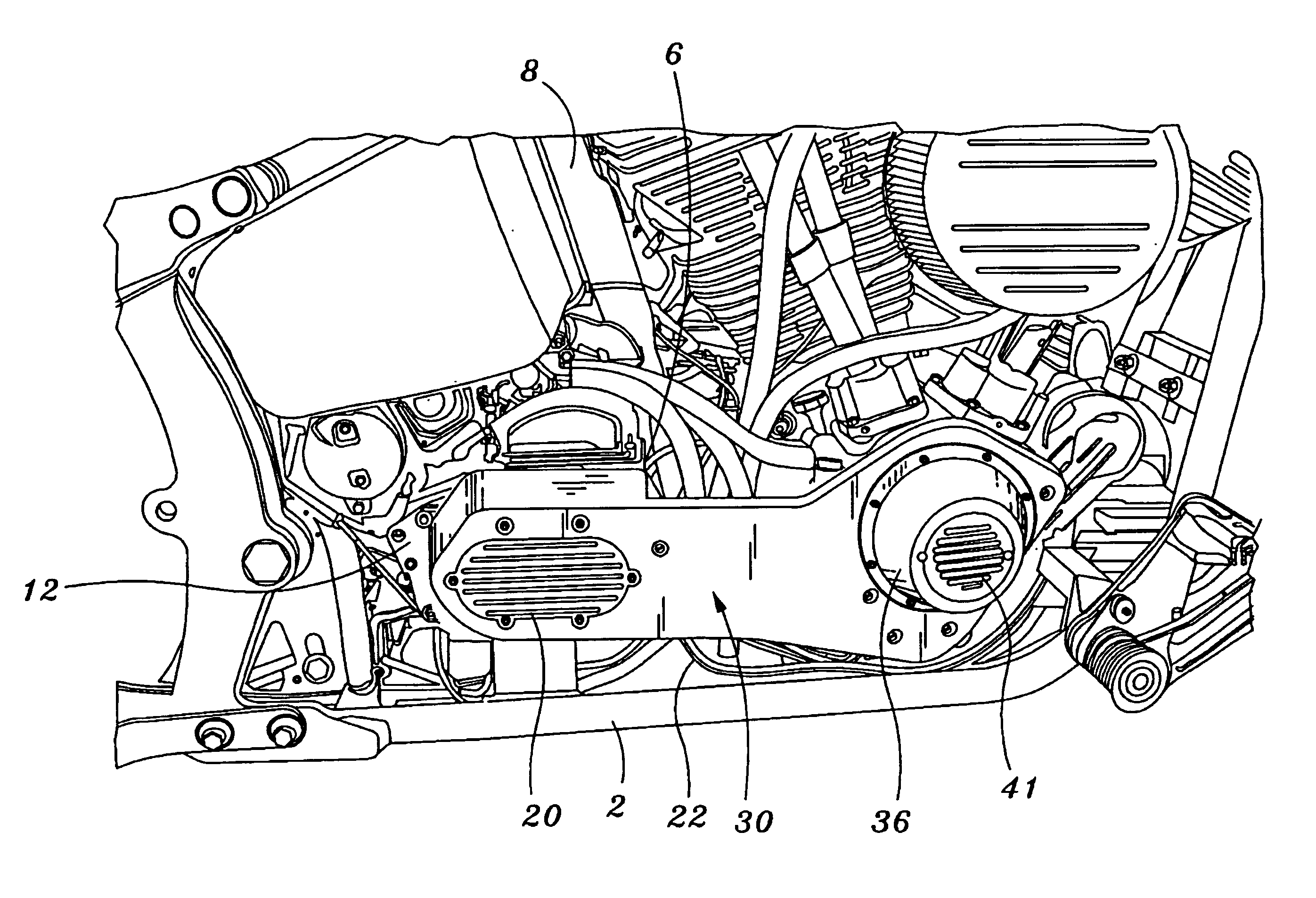
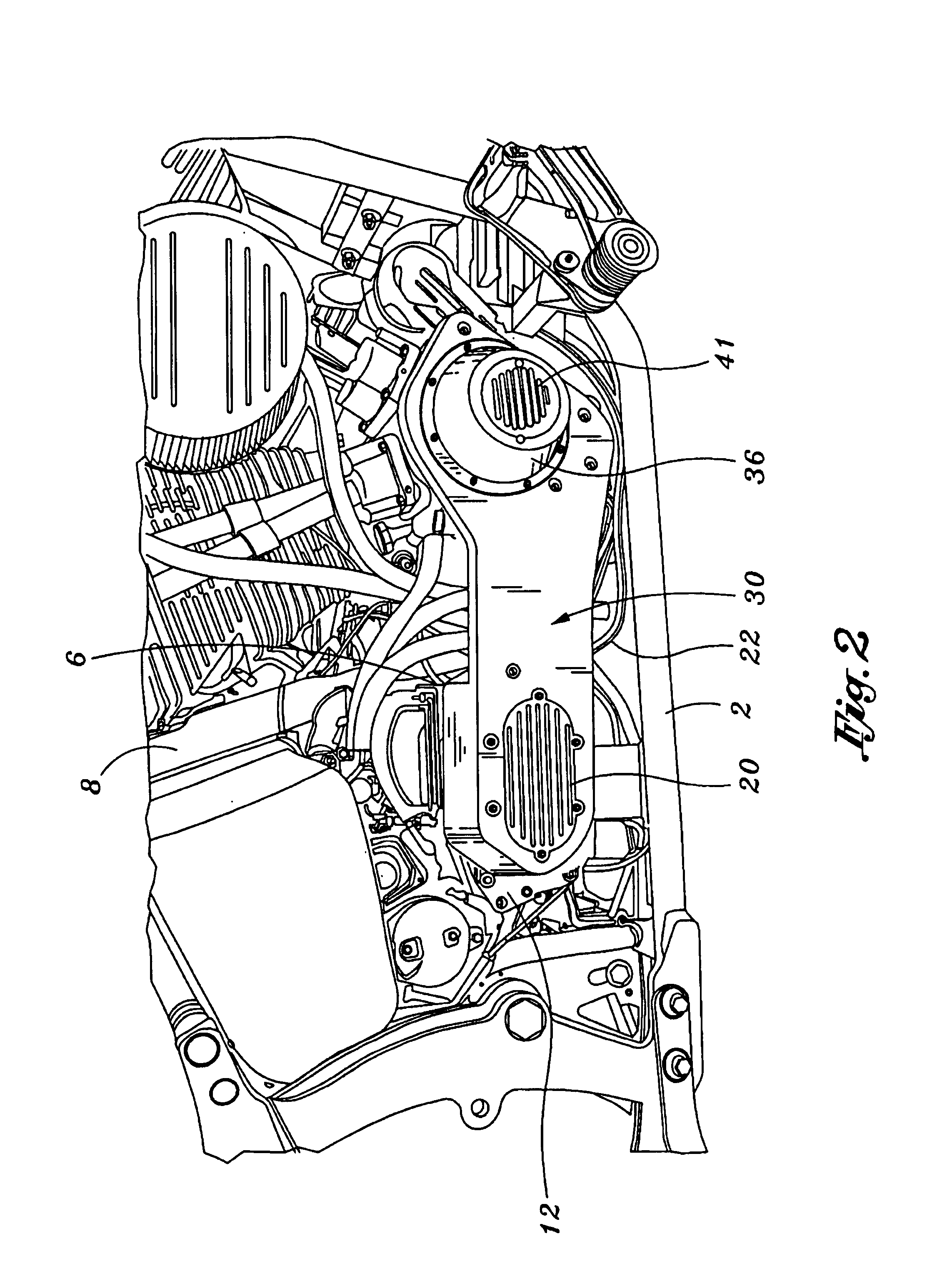
[0015]The aforementioned disadvantages are overcome by providing an interbrace for reducing torquing, twisting, and pivoting between a V-twin engine and a generally separate motorcycle transmission. In a first embodiment of the present invention, an interbrace is provided having an inboard and outboard side. The interbrace includes a forward engine flange portion, a rearward transmission end cap portion which functions as a transmission end cap, and a connecting portion interconnecting the engine flange portion and the transmission end portion. Preferably, the interbrace is milled from billet material.
[0021]According to another aspect of the present invention, a second embodiment of an interbrace may be provided for reducing torquing, twisting, and pivoting between a V-twin engine and a generally separate motorcycle transmission. The interbrace has an inboard and outboard side. The interbrace includes a forward engine flange portion; a rearward transmission end plate flange portion, and a connection portion interconnection the engine flange portion and the transmission end plate flange portion.

Problems solved by technology

However, with the heritage of the V-twin mechanical layout, comes traditional drivetrain deficiencies which have proven disadvantageous and worthy of improvement.
One noticeable weak link of a traditional V-twin layout is the arrangement of the engine-to-transmission interface.
However, the aforementioned engine-to-transmission interface inherently has its disadvantages.
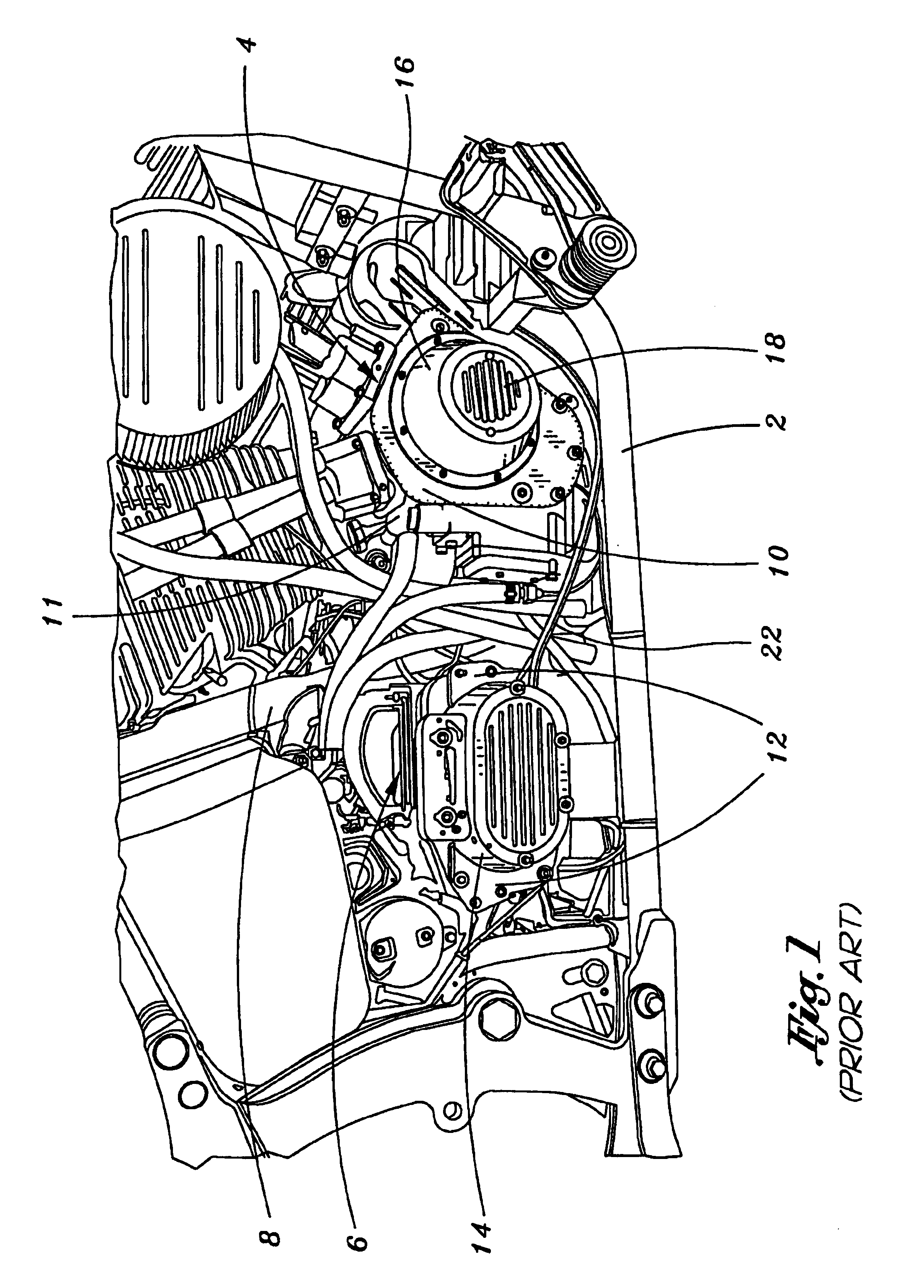
There is minimal direct attachment between the engine and transmission assembly, and the primary drive housing does not provide significant rigidity.
For those motorcycles having a horizontal interface between the engine and transmission assembly, there is also a lack of ability to prevent pivoting of the engine about a horizontal and transverse axis with respect to the motorcycle frame.
Thus, even though a significant advancement for the V-twin engine-to-transmission interface has been made, the aforementioned improvements cannot be economically retrofitted to V-twin engines produced before this significant redesign.
Although the Carlini torque-resisting arm is certainly an innovative and useful product, it still does have its own disadvantages.
Since the Carlini arm is mounted to the engine and transmission in such a limited manner, the overall strengthening effect of the arm is correspondingly limited.
Furthermore, the actual strength of the Carlini arm is limited by the moderate to lightweight construction of the arm.

Method used


Image

  • Motorcycle engine and transmission interbracing member
  • Motorcycle engine and transmission interbracing member
  • Motorcycle engine and transmission interbracing member

Examples


first embodiment

of the Present Invention

[0035]FIGS. 2 through 3A-C depict an exemplary first embodiment interbrace 30. In the first embodiment, the engine end plate 10 and transmission end cap 14 (see FIG. 1) becomes an integral portion of the interbrace 30. Generally, the outer perimeter and shape of the first embodiment 30 resembles that of shoe sole and heel (see FIGS. 3A-C). The interbrace 30 includes an outboard side 46 and an inboard side 48. The interbrace 30 further includes a forward engine end flange portion 32, a connecting portion 44, and transmission end cap portion 42. The interbrace 30 is preferably milled from high strength, light weight alloy billet. However, the interbrace 30 may also be formed by any number of other metal forming processes, known in the motorcycle engine casing and transmission casing manufacturing industry. For example, the interbrace 30 may be forged, die-cast (see FIG. 5) of use a combination of various metal forming and / or milling processes known in the art.

[...

second embodiment

of the Present Invention

[0039]FIG. 5 shows an exemplary second embodiment of an interbrace 60 installed on the well-known V-twin engine and transmission, according to an aspect of the present invention. While, FIGS. 6A-B show a side and top view of the second embodiment interbrace 60, according to an aspect of the present invention. The second embodiment interbrace 60 utilizes a similar engine end plate portion 32, cam gear cover 36, and timing cavity cap 41 similar to that of the first embodiment. A difference with the second embodiment interface 60 (as compared to the first embodiment 30, 31) is that it has a transmission end plate portion 62 which replaces the transmission end plate 12 (see FIG. 1) from a standard transmission 6. Thus, instead of integrally molding the transmission end cap 14 into the interbrace 60 (as is accomplished in the first embodiment interbrace 30), the transmission end plate portion 62 provides a transmission-to-interbrace flange 64 which performs the sa...


PUM


Abstract

An interbrace is provided for reducing torquing, twisting, and pivoting between a V-twin engine and a generally separate motorcycle transmission. A first embodiment of the interbrace includes a forward engine flange portion, a rearward transmission end cap portion which functions as a transmission end cap, and a connecting portion interconnecting the engine flange portion and the transmission end portion. A second embodiment of the interbrace includes a forward engine flange portion, a rearward transmission end plate flange portion, and a connecting portion interconnecting said engine flange portion and said transmission end plate flange portion.

Description

CROSS-REFERENCE TO RELATED APPLICATIONS[0001]Not ApplicableSTATEMENT RE: FEDERALLY SPONSORED RESEARCH / DEVELOPMENT[0002]Not ApplicableBACKGROUND OF THE INVENTION[0003]1. Field of the Invention[0004]The present invention relates to aftermarket engine and transmission interbracing members for HARLEY DAVIDSON type configured motorcycles or the like. In particular, the present invention relates to a structural bracing member which may be attached to the righthand side endplate of a HARLEY DAVIDSON V-twin motor and a righthand side of a transmission, in order to reduce unwanted torquing, pivoting and twisting imparted to the drivetrain through operation of the motorcycle.[0005]2. Background of the Invention[0006]The passion, enthusiasm, and bond that HARLEY DAVIDSON motorcycle owners have for their bikes is well-known. Harley owners and owners of independently manufactured motorcycles and engines based from originally inspired HARLEY DAVIDSON motorcycle designs, continue to modify, custom...

Claims


Application Information

Patent Timeline
Patent Type & Authority Patents(United States)
IPC IPC(8): B60K5/12F02F7/00B62J23/00B62K11/00F02B61/02F02B75/22
CPCB62J23/00F02B61/02F02B75/22
Inventor THURM, KENNETH R.LONGNECKER, SCOTT
Owner THURM KENNETH R
Learn More