Method for producing noil yarn

A production method and technology of staple fiber yarn, applied to spinning machines, continuous winding spinning machines, textiles and papermaking, etc., to achieve the effects of increasing drafting speed, improving the quality of finished yarn, and reducing volume

Inactive Publication Date: 2002-09-04
W SCHLAFHORST & CO
View PDF1 Cites 12 Cited by
  • Summary
  • Abstract
  • Description
  • Claims
  • Application Information

AI Technical Summary

Problems solved by technology

[0016] This known spinning method is of course disadvantageous, the yarn piecing done in the splicer, especially in terms of the yarn structure, always differs significantly from a "normally" spun yarn

Method used


Image

  • Method for producing noil yarn
  • Method for producing noil yarn
  • Method for producing noil yarn

Examples


Embodiment Construction

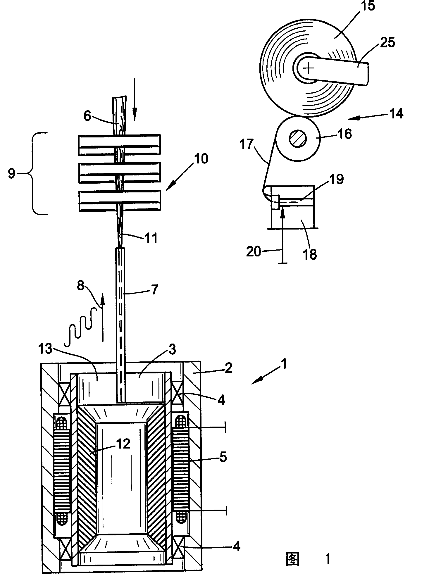
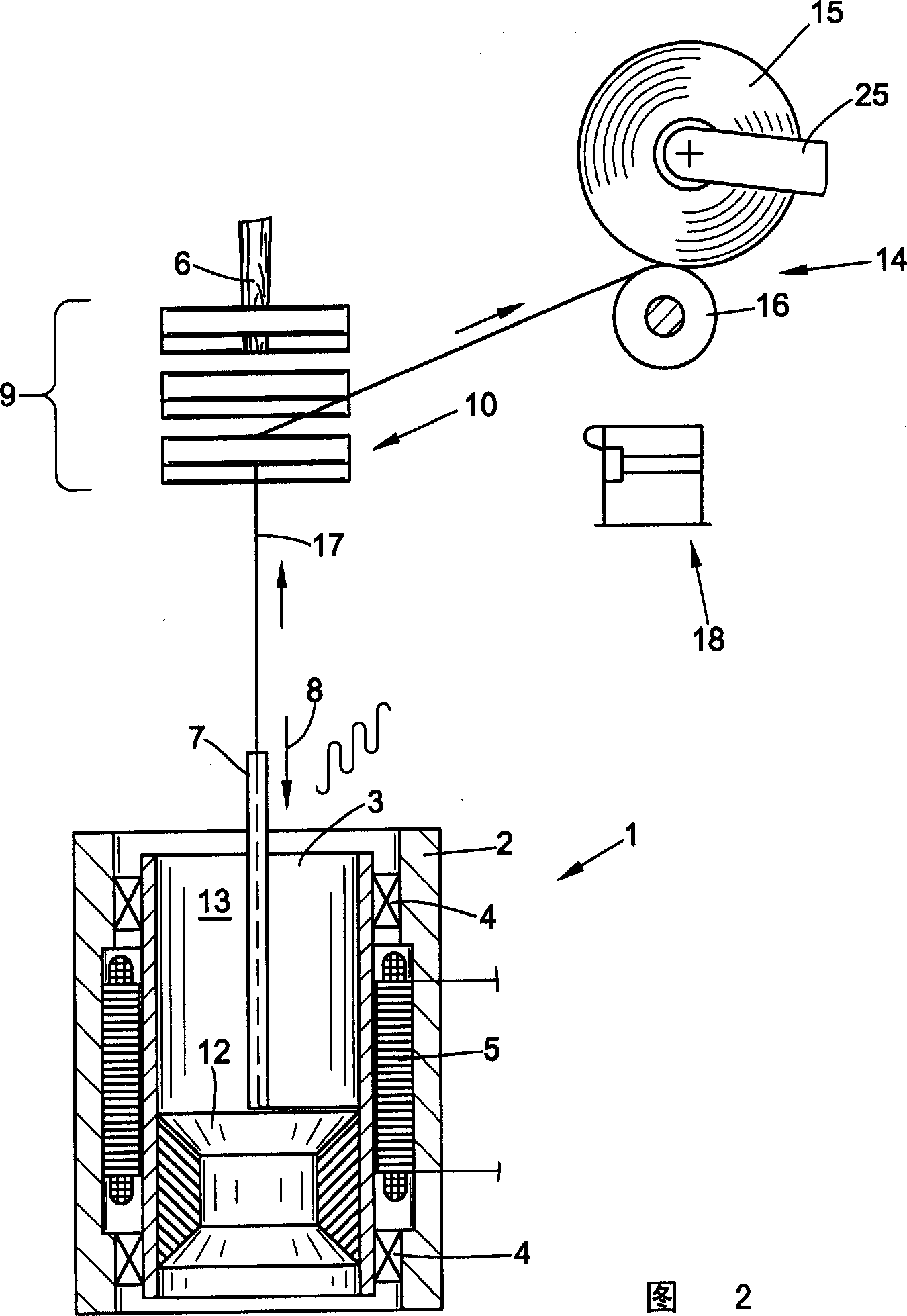
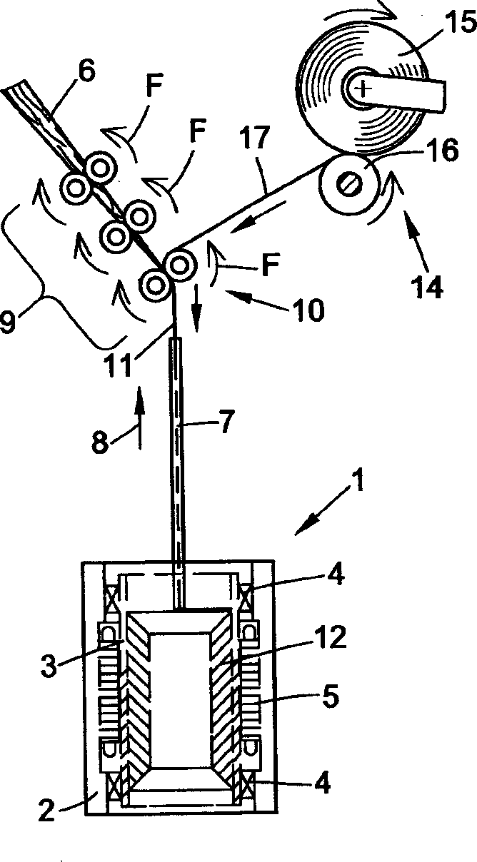
[0042] Figure 1 shows the working positions of a centrifugal spinning machine / winding machine. In addition to a centrifugal spinning device 1, these working spindles also have a winding device 14.

[0043] Usually this known centrifugal spinning device 1 has a spinning centrifuge tank 3 which is supported in the centrifuge tank housing 2 by bearings 4 and driven by an electric motor 5 .

[0044] The bearing 4 can be designed as a magnetic bearing, in which case the supported centrifugal spinning pot 3 is contactless.

[0045] A yarn guide tube 7 can descend in the centrifugal spinning tank, and the yarn guide tube is started by the transmission mechanism 8 shown in the figure, and carries out swinging motion, and can rise or fall along the axial direction simultaneously.

[0046] First, the feed material 6 that has been drafted to the required count by the drafting device 9 reaches the centrifugal spinning tank 3 through the yarn guide tube 7, where it is twisted and wrapped ...


PUM


Abstract

To spin a yarn (17) of staple fibers, a spinning centrifuge (3) is used with a two-stage spinning action. Shortly before the end of the first stage, a prepared yarn end at the yarn wound on a cross wound bobbin (15) is laid in front of the final pair of rollers (10) at the drawing unit (9), and is spliced with the partially-twisted yarn (11) from the first stage. The additionally fed sliver (6) is cut, and the yarn path is changed. In the second stage, the partially-spun yarn cake (12) in the spinning centrifuge is taken off with additional twisting, and wound into a cross wound bobbin. The two-stage spinning process, for a yarn of staple fibers, takes the yarn end from the bobbin into a preparation station (18) before it is spliced with the partially-twisted yarn, where the end of the yarn is untwisted at least partially and thinned out. At the end of the second spinning stage, the yarn is taken off at a higher speed with a lower twist. The draft is temporarily raised at the drawing unit during the splicing phase at the first spinning stage, and at the end of the first spinning stage. The working direction of the final pair of drawing rollers is reversed while the partially-spun yarn is drawn off the spinning cake in the spinning centrifuge. A pressure roller at the final pair of drawing rollers is swung into a take-off setting, to take the partially-spun yarn from the cake in the spinning centrifuge.

Description

technical field [0001] The present invention relates to a method of producing a staple fiber yarn. Background technique [0002] It is known that there are different production methods for the production of short staple yarns. [0003] In addition to ring spinning and rotor spinning, for example centrifugal spinning is a known method for a long time. [0004] The centrifugal spinning method is further divided into two different spinning forms, namely one-step spinning and two-step spinning. [0005] In both spinning forms, the feed material can be a fiber sliver stored in a spinning can, or a roving from a roving bobbin, which is drafted in a drafting device according to the required yarn count, And the yarn is conveyed into the high-speed rotating spinning centrifugal tank through a yarn guide tube mounted on an axially movable support. [0006] The feed material from the outlet of the yarn guide tube forms a spun yarn that wraps around the wall of the centrifugal tank a...

Claims


Application Information

Patent Timeline
Patent Type & Authority Applications(China)
IPC IPC(8): D01H1/00D01H1/06D01H1/08D01H7/02D01H7/74D01H15/00
CPCD01H15/004
Inventor K·科尔策
Owner W SCHLAFHORST & CO
Why Eureka
Try Eureka