Mechanical weightlifting machine

Inactive Publication Date: 2006-05-04
POLIDI RICHARD Z
View PDF11 Cites 11 Cited by
  • Summary
  • Abstract
  • Description
  • Claims
  • Application Information

AI Technical Summary

Benefits of technology

[0009] The object of the invention is to provide an apparatus that can perform functions of a spotter with comfort, precision, and consistency. Therefore, a first objective is to be able to function without using cables. A second objective is to be able to apply various different forces to the exerciser's weight throughout a single routine, possibly including a force great enough to raise the weight without assistance from the exerciser. A third objective is to be able to vary this assistance quickly. A fourth objective is to be able to function without restricting the exerciser's range of motion. A fifth objective is to function in a manner that safe and visible.

Problems solved by technology

Many weightlifters face the drawback of not having skilled spotters to help them on a consistent basis.
As a result, these weightlifters sometimes do not achieve the results they seek and grow disheartened with the sport.
Unfortunately, it is impossible for only a few trainers to provide the services of a spotter to all these weightlifters at any one time.
Unless the cables are continuously taut throughout the exercise, they can move suddenly, interfering with the exerciser's motion and causing discomfort.
Several of these machines also are not versatile enough to perform all the functions of a spotter.
In particular, a machine that uses a motor to pull up a weight can not perform several functions of a spotter.
Machines with pneumatic devices unfortunately may require several seconds to vary the amount of assistance given to the exerciser, whereas a human spotter is able to provide the assistance immediately.

Method used


Image

  • Mechanical weightlifting machine
  • Mechanical weightlifting machine
  • Mechanical weightlifting machine

Examples


Embodiment Construction

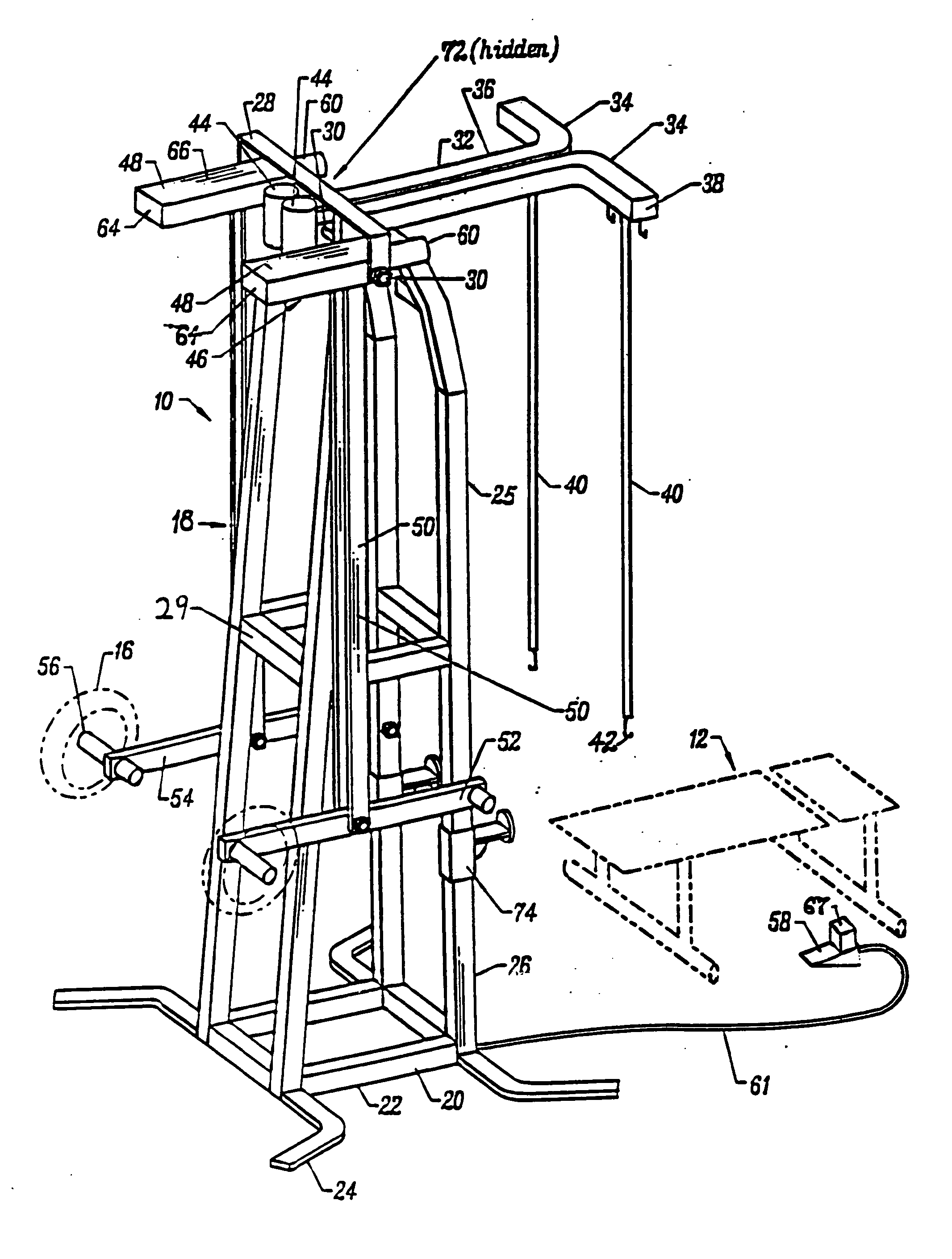
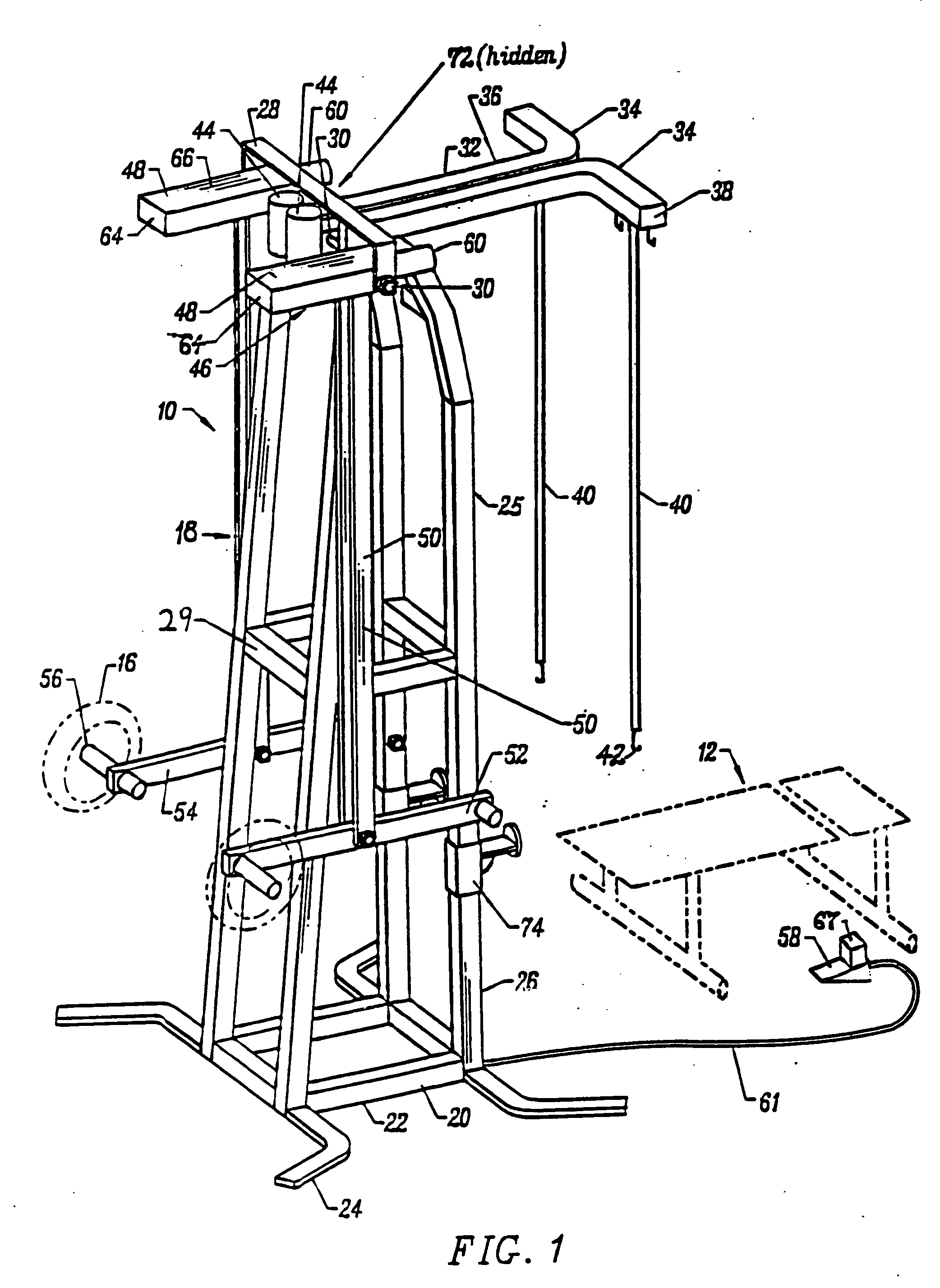
[0032] The mechanical weightlifting machine of this invention, designated generally by the reference numeral 10, functions as a mechanical spotter. The mechanical weightlifting machine 10, hereinafter the spotter, is used in many routines with a conventional bench 12 shown in phantom in FIG. 1. The. spotter can also accommodate inclining and declining benches, upright seats, and a standing exerciser without any bench. The spotter is used with weights in the form of conventional plates or disks 16, two of which are shown in phantom in FIG. 1.

[0033] The spotter 10 is constructed with a support frame 18 having a base 20 formed by interconnected box tube members 22 and wing-like stabilizer members 24. The support frame 18 has a vertical support structure 25 formed of substantially vertical box tube members 26 having a generally rectangular or pyramidal structure with an apex cross beam 28. Box tube members 30 located approximately midway on the vertical support 24 provide the necessary...


PUM


Abstract

A mechanical weightlifting machine in which the machine has a support structure with an elevated pivot having a pivot axis and an articulating mechanism engaging the pivot. The articulating mechanism having at least one articulating structure with a lever arm that has a depending link connected to the weight being used by the weightlifter. The articulating structure having an adjustment mechanism with a displaceable connection device connected to a counterweight. The adjustment mechanism having means for moving the displaceable connection device relative to the pivot axis and actuation means for actuating the means for moving, in order to vary the effective weight removed from or applied to the weight being used by the weightlifter.

Description

RELATED APPLICATIONS [0001] This patent application hereby incorporates by reference the following U.S. patent applications and issued U.S. patents: application Ser. No. 09 / 945,779; application Ser. No. 09 / 277,806—now U.S. Pat. No. 6,283,898; application Ser. No. 09 / 128,167; and application Ser. No. 08 / 905,461—now U.S. Pat. No. 5,788,616, FIELD OF THE INVENTION [0002] This invention relates to a machine used in weightlifting exercises. BACKGROUND OF THE INVENTION [0003] A weightlifter can benefit from the active involvement of a second person, commonly known as a spotter, during a weightlifting routine. This spotter serves two basic functions. The first is to prevent injury to the weightlifter. The second is to prolong the weightlifting exercise by providing aid to the weightlifter during the weightlifting repetitions. The second function allows the weightlifter to complete additional repetitions after his or her muscles have begun to fatigue. Completing repetitions with slightl...

Claims


Application Information

Patent Timeline
IPC IPC(8): A63B21/06A63B21/08
CPCA63B21/0615A63B21/08A63B21/1492A63B21/159A63B23/03525A63B24/00A63B2021/0616A63B21/0616A63B21/4047
Inventor POLIDI, RICHARD Z.
Owner POLIDI RICHARD Z
Why Eureka
Try Eureka