
Method for wiring allocation and switch configuration in a multiprocessor environment

a multiprocessor environment and wiring allocation technology, applied in the field of multiprocessor environments, can solve the problems of limited communication channels within multiprocessors and limited ability of processing elements to communicate with other processing elements

Inactive Publication Date: 2006-05-04
IBM CORP
View PDF10 Cites 6 Cited by
  • Summary
  • Abstract
  • Description
  • Claims
  • Application Information

AI Technical Summary

Benefits of technology

[0050] In another aspect of the present invention the means are operative responsive to a request for a partition with a uniq

Problems solved by technology

Communication channels within a multiprocessor are often limited by geometric constraints.
For example, processing elements are typically limited in their ability to communicate with other processing elements, and may only be able to communicate with those processing elements physically adjacent to them, such as in a one-dimensional row of processing elements, where each processing element has at most two neighbors with which it may communicate.

Method used


Image

  • Method for wiring allocation and switch configuration in a multiprocessor environment
  • Method for wiring allocation and switch configuration in a multiprocessor environment
  • Method for wiring allocation and switch configuration in a multiprocessor environment

Examples


Embodiment Construction

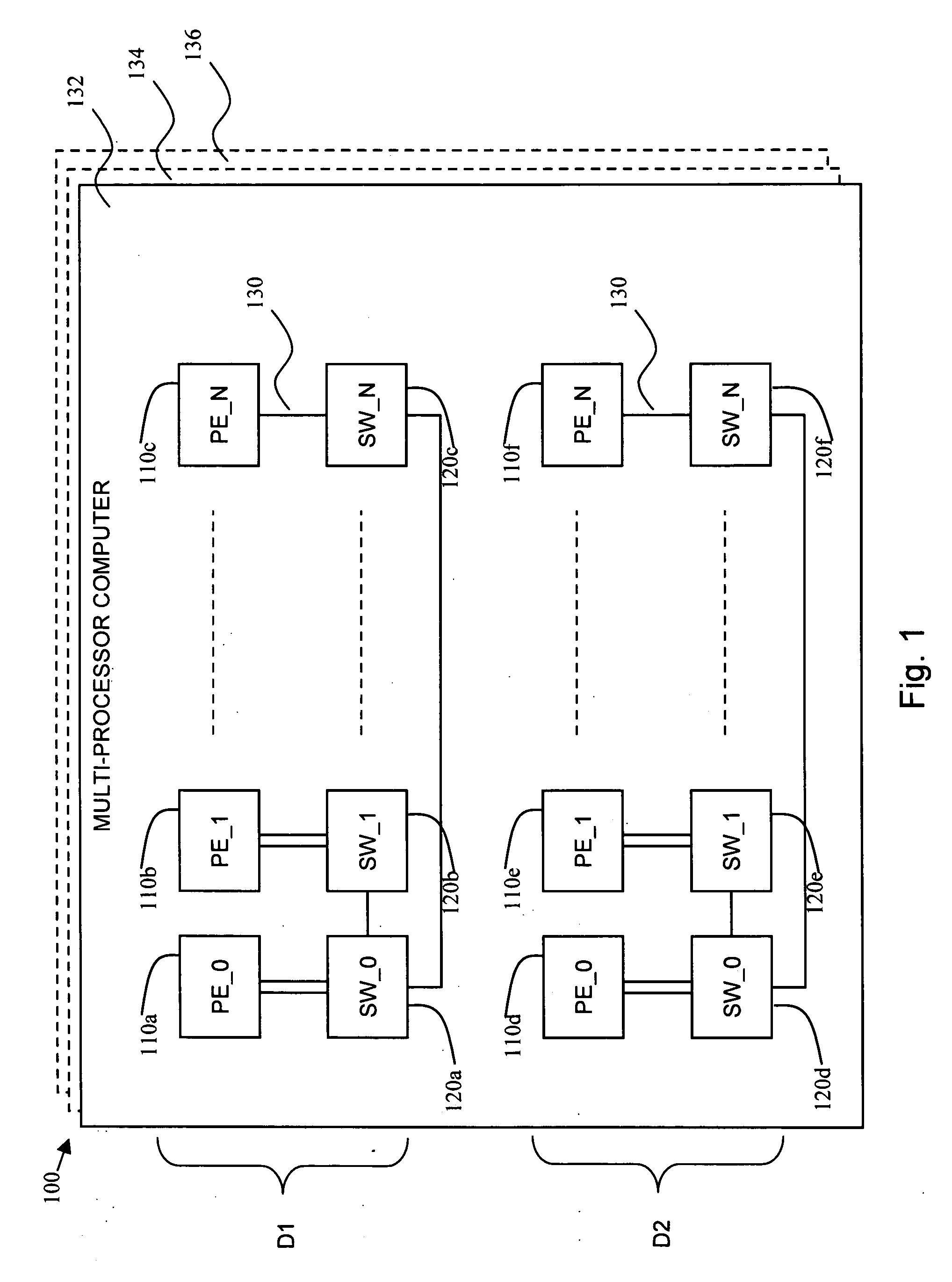
[0065] Reference is now made to FIG. 1, which is a simplified pictorial illustration of a multiprocessor computer, constructed and operative in accordance with a preferred embodiment of the present invention. A multiprocessor computer 100 is shown having a single, two-dimensional plane 132 of processing elements 110, switches 120, and wires 130, although multiprocessor computer 100 may have additional dimensions as well, such as is shown by planes 134 and 136. While the present invention is described with reference to a two-dimensional plane, the invention is not limited to a two-dimensional arrangement, and may be understood with respect to any multi-dimensional arrangement.

[0066] In multiprocessor computer 100, a set of processing elements 110a through 110f, where each processing element 110 may be a single processor or a multiprocessor, and a set of switches 120a through 120f, are shown. Processing elements 110 typically utilize a private memory module to store data and are capa...


PUM


Abstract

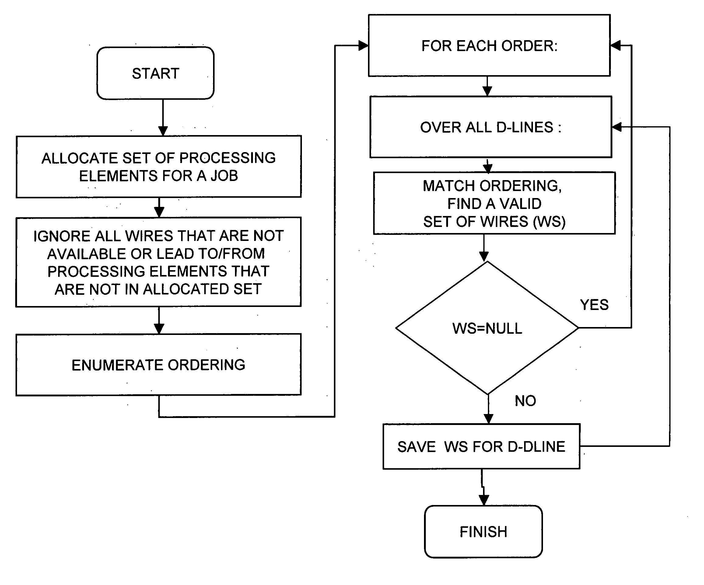
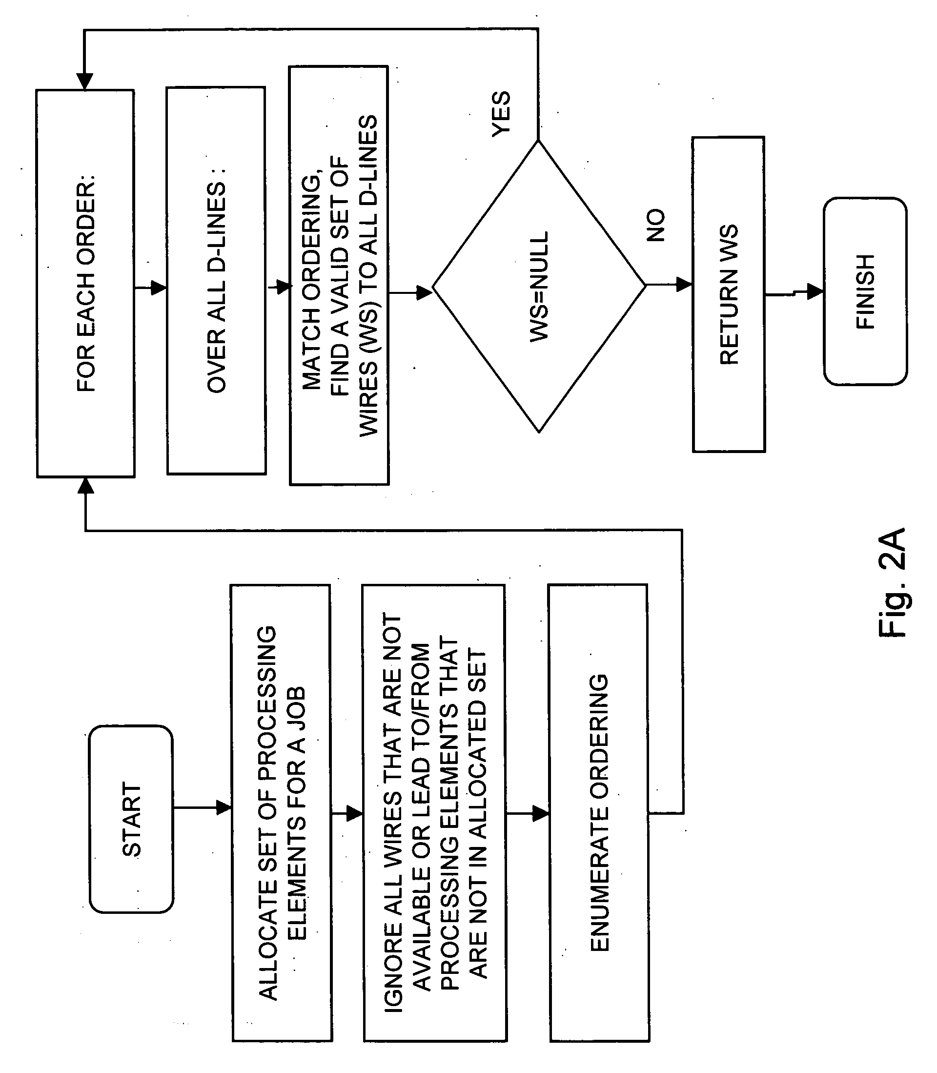
A method for wiring allocation and switch configuration in a multiprocessor computer, the method including employing depth-first tree traversal to determine a plurality of paths among a plurality of processing elements allocated to a job along a plurality of switches and wires in a plurality of D-lines, and selecting one of the paths in accordance with at least one selection criterion.

Description

STATEMENT REGARDING FEDERALLY SPONSORED RESEARCH OR DEVELOPMENT [0001] This invention was made with U.S. government support under Contract No. B517552 awarded by the U.S. Department of Energy. The U.S. Government has certain rights in this invention.FIELD OF THE INVENTION [0002] The present invention relates to multiprocessor environments in general, and more particularly to the allocation and configuration of elements within multiprocessor environments. BACKGROUND OF THE INVENTION[0003] Complex computational problems can often be divided and distributed among multiple processing elements, where each processing element may work independently or in conjunction with other processing elements. A multiprocessor computer with flexible resources may group internal resources into one or more partitions, and configure and assign each partition to be responsible for a particular computational task or job. [0004] Communication channels within a multiprocessor are often limited by geometric co...

Claims


Application Information

Patent Timeline
IPC IPC(8): G06F15/00
CPCG06F9/5061G06F2209/5012
Inventor ARIDOR, YARIVDOMANY, TAMARFRACHTENBERG, EITANGAL, YOAVSHMUELI, EDISTOCKMEYER, LARRY JOSEPHSTOCKMEYER, ROBERT E.
Owner IBM CORP
Learn More