
Multiprocessor node controller circuit and method

a node controller and multi-processor technology, applied in data switching networks, memory adressing/allocation/relocation, instruments, etc., can solve problems such as difficulty in imposing a deterministic order of events when necessary in such a system

Inactive Publication Date: 2005-03-10
HEWLETT-PACKARD ENTERPRISE DEV LP +1
View PDF13 Cites 137 Cited by
  • Summary
  • Abstract
  • Description
  • Claims
  • Application Information

AI Technical Summary

Benefits of technology

The present invention provides a method and apparatus for highly parallel processing using a single chip that includes a crossbar unit and multiple processor ports. This design allows for direct communication between processors, input / output, and memory, resulting in faster data transmission and lower latency. The chip can be designed for small or large systems and is more cost-effective to build. The method includes transmitting data between the memory port and processor ports, as well as between the memory port and input / output port. The chip can be connected through a router network or a single chip. The technical effects of this invention include faster data processing, improved performance-cost benefits, and better scalability.

Problems solved by technology

While the power of a multiple-instruction multiple-data (MIMD) MP computer system lies in its ability to execute independent threads of code simultaneously, the inherently asynchronous states of the PEs (with respect to each other) makes it difficult in such a system to enforce a deterministic order of events when necessary.

Method used


Image

  • Multiprocessor node controller circuit and method
  • Multiprocessor node controller circuit and method
  • Multiprocessor node controller circuit and method

Examples


Embodiment Construction

In the following detailed description of the preferred embodiments, reference is made to the accompanying drawings that form a part hereof, and in which are shown by way of illustration specific embodiments in which the invention may be practiced. It is understood that other embodiments may be utilized and structural changes may be made without departing from the scope of the present invention.

Some embodiments of the present invention include routers, networks, and synchronization apparatus and methods as described further in copending U.S. patent application Ser. No. 08 / 972,010 filed Nov. 17, 1997, which is hereby incorporated by reference.

Some embodiments implement multiprocessor systems, that generally do not use a coherent cache model. Other embodiments include cache coherence mechanisms and methods such as described in application Ser. No. 08 / 971,184 filed Nov. 17, 1997 entitled “MULTI-DIMENSIONAL CACHE COHERENCE DIRECTORY STRUCTURE”, which is hereby incorporated by refere...


PUM


Abstract

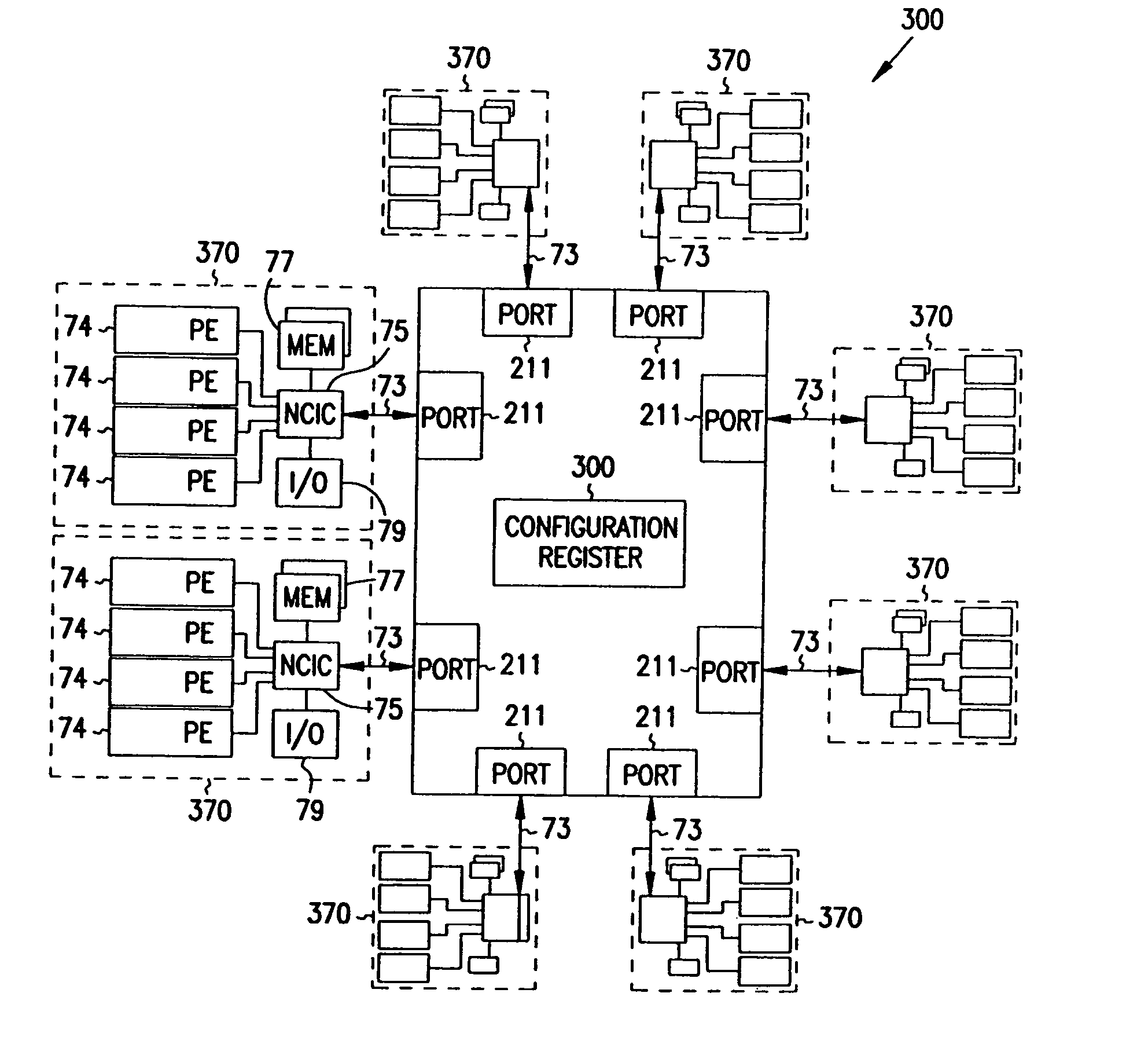
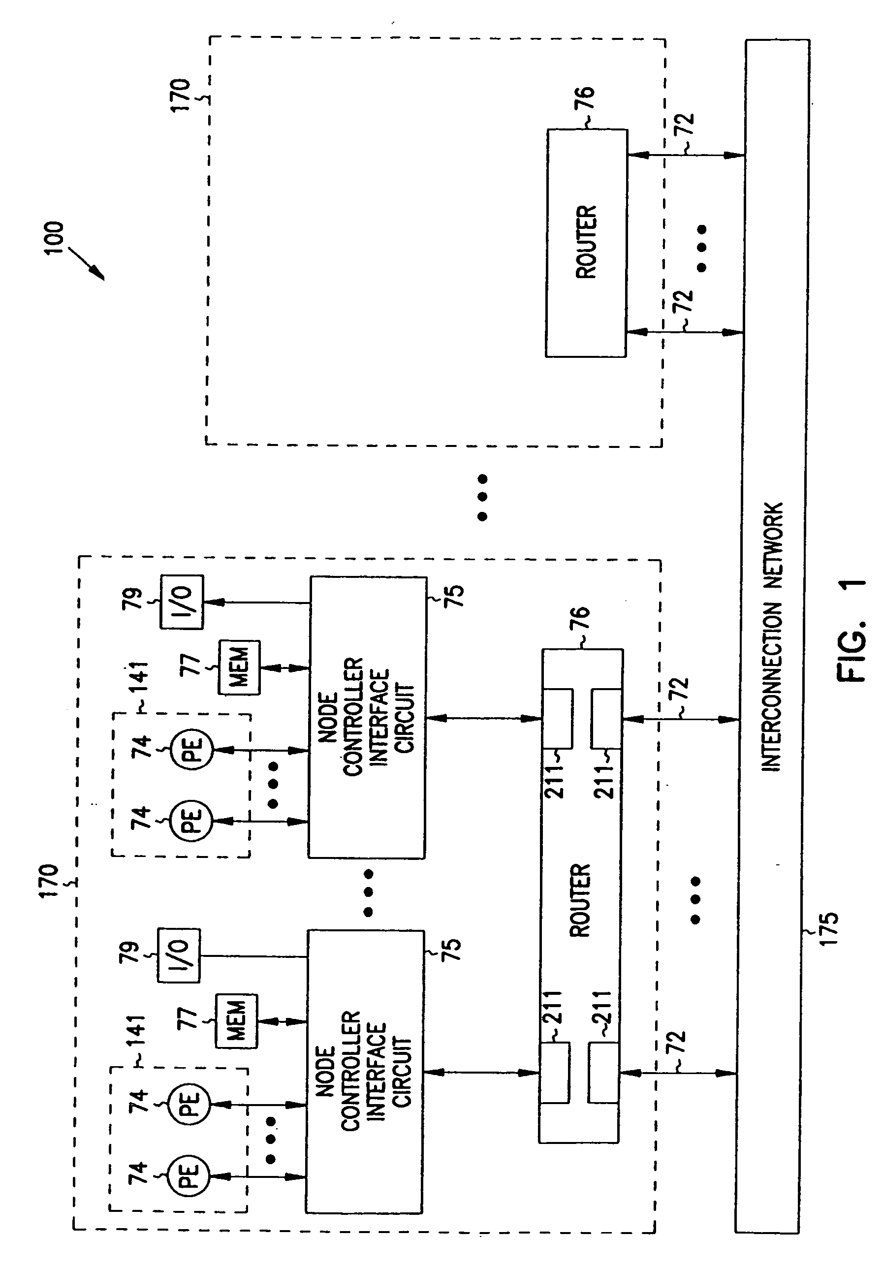
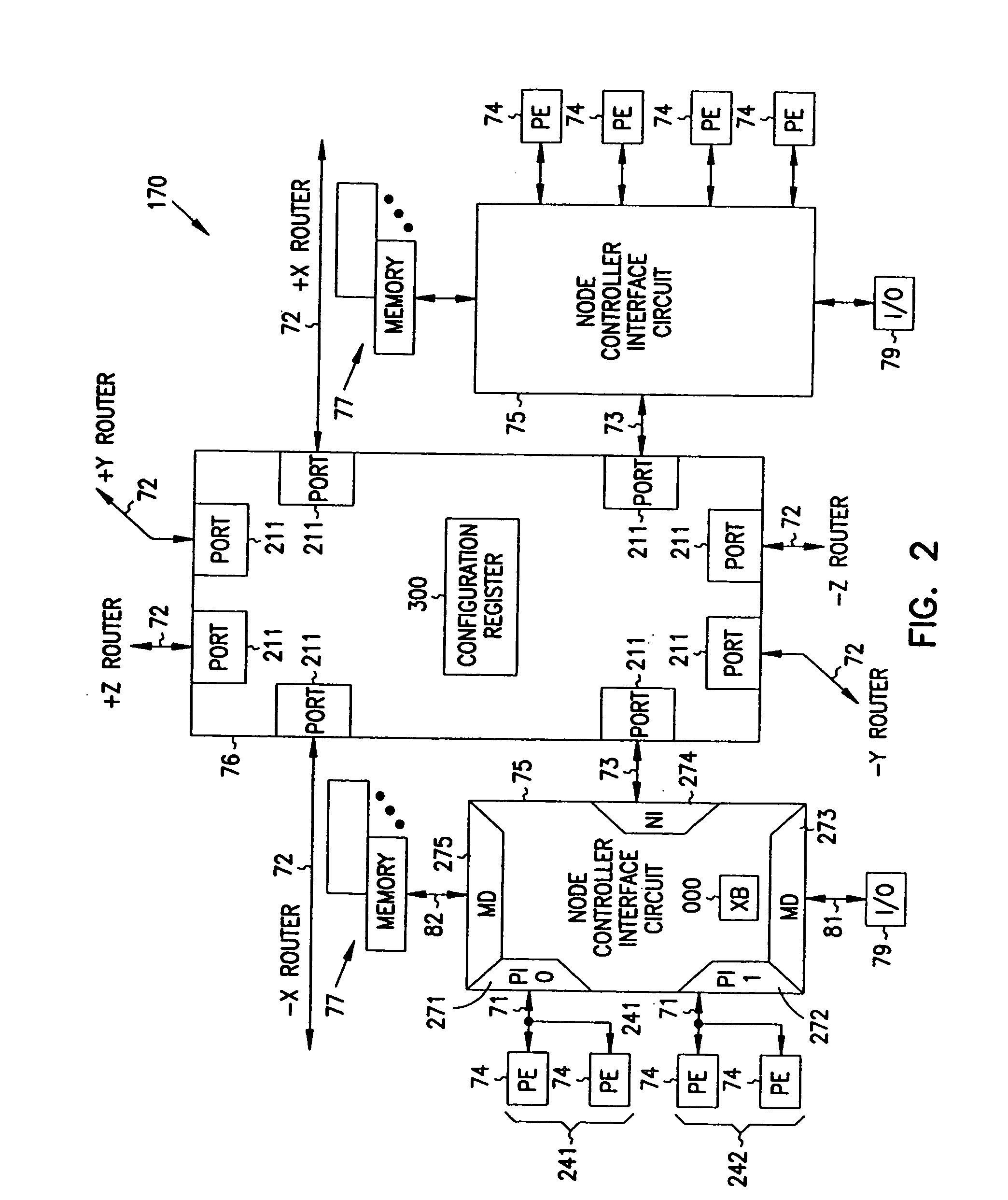
Improved method and apparatus for parallel processing. One embodiment provides a multiprocessor computer system that includes a first and second node controller, a number of processors being connected to each node controller, a memory connected to each controller, a first input / output system connected to the first node controller, and a communications network connected between the node controllers. The first node controller includes: a crossbar unit to which are connected a memory port, an input / output port, a network port, and a plurality of independent processor ports. A first and a second processor port connected between the crossbar unit and a first subset and a second subset, respectively, of the processors. In some embodiments of the system, the first node controller is fabricated onto a single integrated-circuit chip. Optionally, the memory is packaged on plugable memory / directory cards wherein each card includes a plurality of memory chips including a first subset dedicated to holding memory data and a second subset dedicated to holding directory data. Further, the memory port includes a memory data port including a memory data bus and a memory address bus coupled to the first subset of memory chips, and a directory data port including a directory data bus and a directory address bus coupled to the second subset of memory chips. In some such embodiments, the ratio of (memory data space) to (directory data space) on each card is set to a value that is based on a size of the multiprocessor computer system.

Description

FIELD OF THE INVENTION The present invention relates to methods and apparatus for parallel multiprocessor computer systems and more specifically to a multiprocessor node-controller circuit and method. BACKGROUND OF THE INVENTION Multiprocessor (MP) systems are computing systems comprised of a few or up to hundreds or thousands of processing elements (PEs). While the power of a multiple-instruction multiple-data (MIMD) MP computer system lies in its ability to execute independent threads of code simultaneously, the inherently asynchronous states of the PEs (with respect to each other) makes it difficult in such a system to enforce a deterministic order of events when necessary. Program sequences involving interaction between multiple PEs such as coordinated communication, sequential access to shared resources, controlled transitions between parallel regions, etc., may require synchronization (such as barrier and / or eureka synchronization) of the PEs in order to assure proper execut...

Claims


Application Information

Patent Timeline
Patent Type & Authority Applications(United States)
IPC IPC(8): G06F12/08G06F12/06G06F13/36G06F15/173G06F15/177G06F15/80
CPCG06F15/17381G06F15/17343
Inventor DENEROFF, MARTIN M.KALDANI, GIVARGIS G.KOREN, YUVALMCCRACKEN, DAVID EDWARDVENKATARAMAN, SWAMINATHAN
Owner HEWLETT-PACKARD ENTERPRISE DEV LP
Learn More