
Three-dimensional imaging method for multi-transmitting and multi-receiving synthetic aperture radar

A synthetic aperture radar, multi-transmit and multi-receive technology, applied in the direction of re-radiation, radio wave reflection/re-radiation, measurement devices, etc., can solve problems such as defocus, unfavorable parallel processing, position offset, etc., to reduce the amount of calculation , is conducive to the effect of parallel processing

Active Publication Date: 2019-09-24
NAT UNIV OF DEFENSE TECH
View PDF9 Cites 4 Cited by
  • Summary
  • Abstract
  • Description
  • Claims
  • Application Information

AI Technical Summary

Problems solved by technology

The distance migration algorithm has the following disadvantages: it needs to calculate the Fourier transform of the measurement data along the scanning direction, so the imaging process can only be started after the measurement data is collected along the scanning direction; it can only be used when the scanning trajectory of the multi-input and multi-receiving array is a straight line Multi-transmitter multi-receiver SAR imaging system, which is only suitable for systems with equivalent antenna aperture as a plane, is not conducive to parallel processing
Approximation-based methods will lead to a decrease in the accuracy of imaging results, such as defocusing and position shifting at some imaging positions, and cannot be used for short-distance precise imaging

Method used


Image

  • Three-dimensional imaging method for multi-transmitting and multi-receiving synthetic aperture radar
  • Three-dimensional imaging method for multi-transmitting and multi-receiving synthetic aperture radar

Examples


Embodiment Construction

[0021] Below in conjunction with accompanying drawing and the example of the present invention, the present invention will be further described.

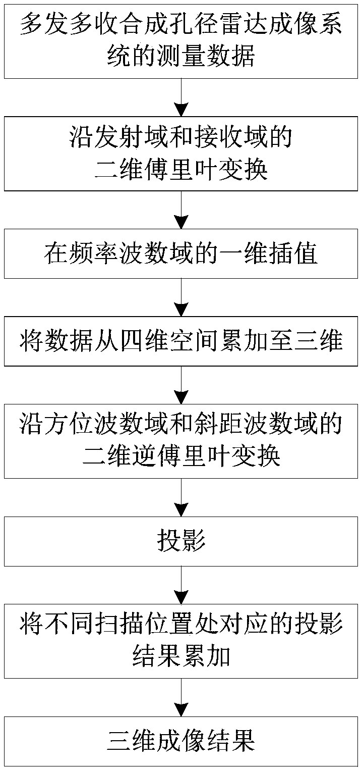
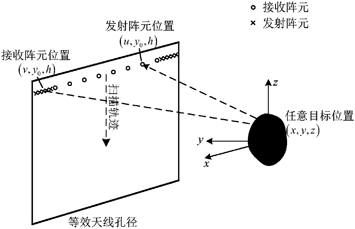
[0022] figure 1 It is a flowchart of the method of the present invention. figure 2 It is the geometric relationship diagram when the multi-send and multi-receive array scans along a straight line. O represents the origin of the coordinates, the x-axis represents the azimuth direction, the y-axis represents the distance direction, and the z-axis represents the height direction. The send and receive array is parallel to the x-axis, at a distance of y from the origin 0 scan along the z-axis, and the z-axis coordinate of the multi-send and multi-receive array is h. The coordinates of the transmitting array element are (u, y 0 ,h), the coordinates of the receiving element are (v,y 0 ,h), the coordinates of any point on the target are (x,y,z). Assuming that the transmitted signal is a step frequency signal, the measurement data of ...


PUM


Abstract

The invention discloses a three-dimensional imaging method for a multi-transmitting and multi-receiving synthetic aperture radar. The method includes the following steps: carrying out two-dimensional imaging on echo data collected by a multi-transmitting and multi-receiving array at all scanning positions; projecting two-dimensional imaging results which are obtained after processing and correspond to all the scanning positions to three-dimensional space; and adding three-dimensional imaging results which are obtained after processing and correspond to all the scanning positions after processing. The three-dimensional imaging method of the invention can avoid calculating Fourier transform of measurement of a multi-transmitting and multi-receiving synthetic aperture radar imaging system along a scanning direction, can perform multi-transmitting and multi-receiving array scanning and imaging processing at the same time, is suitable for the multi-transmitting and multi-receiving synthetic aperture radar imaging system with a multi-transmitting and multi-receiving array scanning track being a straight line or a curve, which means that an equivalent antenna aperture is a plane or a curved surface, reduces the calculation amount and is beneficial to parallel processing.

Description

technical field [0001] The invention belongs to the field of radar imaging methods, in particular to a three-dimensional imaging method for multi-transmission and multi-reception synthetic aperture radar. Background technique [0002] The multi-transmission and multi-reception synthetic aperture radar uses multi-transmission and multi-reception array scanning to form a two-dimensional equivalent antenna aperture, and uses broadband signals to achieve three-dimensional imaging of the target. The scanning trajectory of the array is uncertain, which can be a straight line or a curve. The surface formed by the scanning of the multi-firing and multi-receiving SAR is the equivalent antenna aperture of the multi-firing and multi-receiving SAR. When the scanning trajectory of the multi-transmission and multi-reception array is a straight line, the equivalent antenna aperture formed is a plane; when the scanning trajectory of the multi-transmission and multi-reception array is circul...

Claims


Application Information

Patent Timeline
IPC IPC(8): G01S13/90
CPCG01S13/90G01S13/9058G01S13/9004
Inventor 周剑雄朱荣强
Owner NAT UNIV OF DEFENSE TECH
Learn More