
Multiprocessor system in which a cache serving as a highest point of coherency is indicated by a snoop response

a multi-processor computer system and cache technology, applied in computing, memory adressing/allocation/relocation, instruments, etc., can solve the problems of processing elements that are easy to miss, increase the bus bandwidth, and improve the latency

Inactive Publication Date: 2002-06-11
IBM CORP
View PDF15 Cites 148 Cited by
  • Summary
  • Abstract
  • Description
  • Claims
  • Application Information

AI Technical Summary

Problems solved by technology

However, it is possible for a processing element to miss a write to the memory location.
This procedure not only results in better latency, but also increased bus bandwidth.
As the number of processing units in multiprocessor systems has increased, the interconnection topologies for the processing units, cache and system memory have become quite complicated, and can lead to inefficiencies in the handling of coherency operations.
In such systems, all snooping devices may not receive a master's request at the same time due to different delays through the interconnection topology.
The intricate nature of these connections makes it more difficult to collect all responses in a timely manner, and form a proper combined response, particularly when a device in one processing cluster contains a value that is requested by a device in a different processing cluster.
The difficulty is compounded if two masters simultaneously issue conflicting access requests to different sectors of the same cache line.
The result is an overall reduction in system performance.
Providing a central point of coherency is additionally much more problematic for systems with distributed memory, such as non-uniform memory access (NUMA) systems wherein RAM is divided among two or more memory arrays allocated to respective processing units.

Method used


Image

  • Multiprocessor system in which a cache serving as a highest point of coherency is indicated by a snoop response
  • Multiprocessor system in which a cache serving as a highest point of coherency is indicated by a snoop response
  • Multiprocessor system in which a cache serving as a highest point of coherency is indicated by a snoop response

Examples


Embodiment Construction

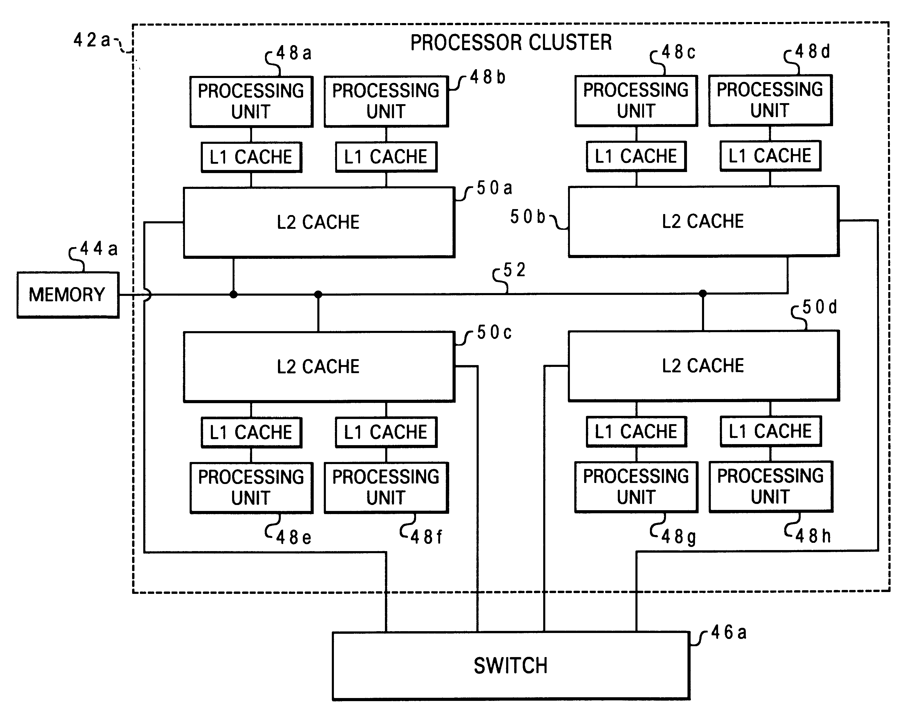
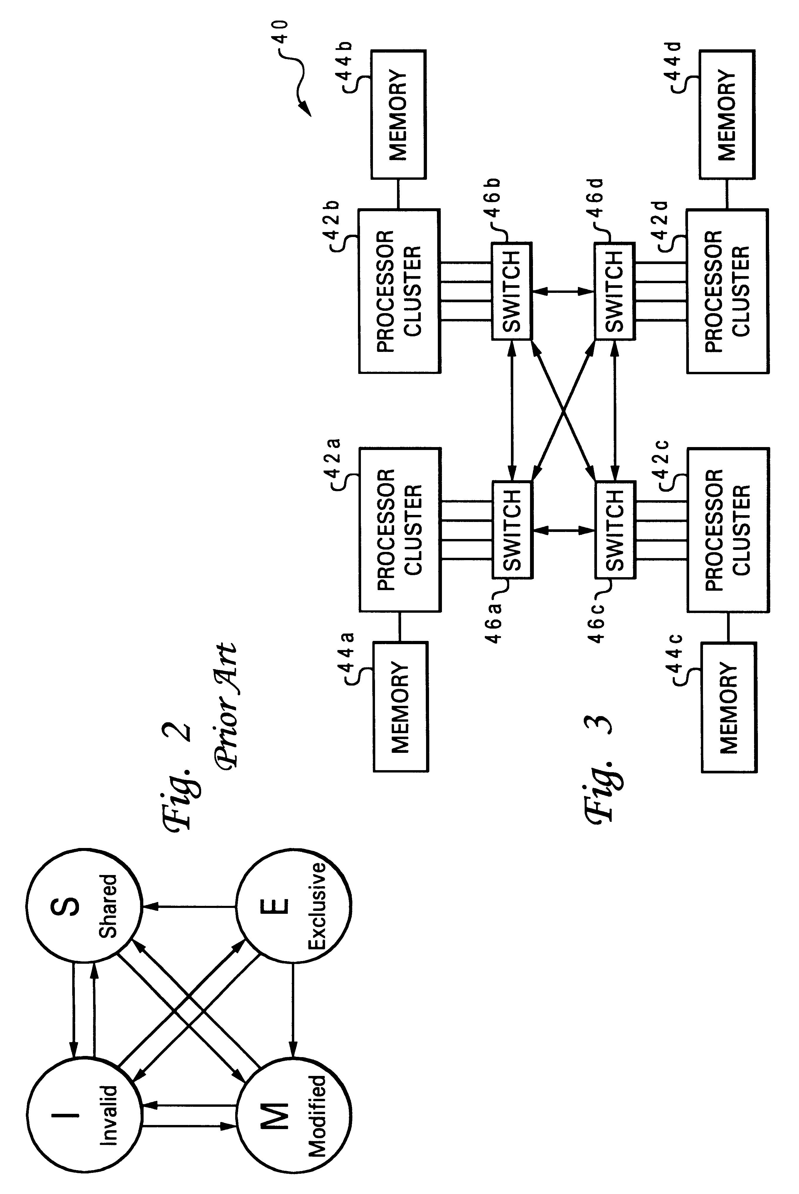
With reference now to the FIG., and in particular with reference to FIG. 3, there is depicted one embodiment 40 of a multiprocessor computer system constructed in accordance with the present invention. Computer system 40 comprises a plurality of processor clusters 42a, 42b, 42c and 42d, and a distributed memory including mutually exclusive memory arrays 44a, 44b, 44c and 44d. Each memory array is associated with a respective processor cluster. The processor clusters are coupled using four switches 46a, 46b, 46c and 46d. Computer system 40 further includes a plurality of input / output (I / O) devices which are not shown for simplicity, that may be accessed via an interconnect bus connected to the switches. The present invention is directed to a method of handling cache operations in a memory-coherent, multiprocessor system such as the system of FIG. 4, but the present invention could be applied to computer systems that have additional hardware components not shown in FIG. 4, or having a...


PUM


Abstract

A method of maintaining cache coherency, by designating one cache that owns a line as a highest point of coherency (HPC) for a particular memory block, and sending a snoop response from the cache indicating that it is currently the HPC for the memory block and can service a request. The designation may be performed in response to a particular coherency state assigned to the cache line, or based on the setting of a coherency token bit for the cache line. The processing units may be grouped into clusters, while the memory is distributed using memory arrays associated with respective clusters. One memory array is designated as the lowest point of coherency (LPC) for the memory block (i.e., a fixed assignment) while the cache designated as the HPC is dynamic (i.e., changes as different caches gain ownership of the line). An acknowledgement snoop response is sent from the LPC memory array, and a combined response is returned to the requesting device which gives priority to the HPC snoop response over the LPC snoop response.

Description

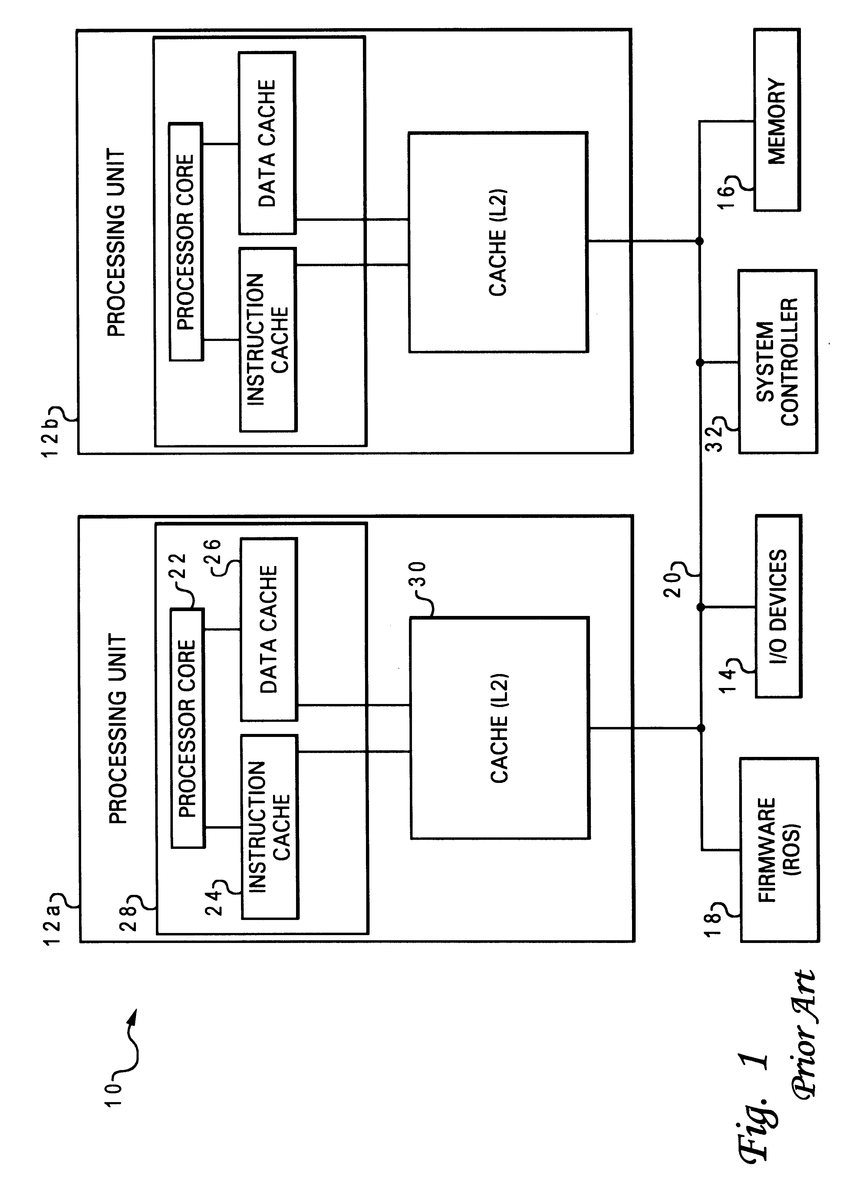
1. Field of the InventionThe present invention generally relates to computer systems, specifically to a method of maintaining cache coherency in a multiprocessor computer system, and more particularly to an improved cache coherency protocol which allows the point of coherency (or coherency control) to dynamically float so as to more efficiently handle cache operations in systems with complicated interconnection topologies.2. Description of Related ArtThe basic structure of a conventional multiprocessor computer system 10 is shown in FIG. 1. Computer system 10 has several processing units, two of which 12a and 12b are depicted, which are connected to various peripheral devices, including input / output (I / O) devices 14 (such as a display monitor, keyboard, graphical pointer (mouse), and a permanent storage device or hard disk), memory device 16 (such as random access memory or RAM) that is used by the processing units to carry out program instructions, and firmware 18 whose primary pur...

Claims


Application Information

Patent Timeline
IPC IPC(8): G06F12/08
CPCG06F12/0831G06F12/0813G06F2212/2542
Inventor ARIMILLI, RAVI KUMARCLARK, LEO JAMESFIELDS, JR., JAMES STEPHENGUTHRIE, GUY LYNN
Owner IBM CORP
Learn More