Tape measure with automatic blade extension mechanism
a technology of automatic extension and tape measure, which is applied in the direction of mechanical means, instruments, measurement devices, etc., can solve the problems of high manufacturing cost of tape measure, inconvenient use, and inability to measure objects using tape measure, so as to increase working efficiency, ensure safety, and facilitate use
- Summary
- Abstract
- Description
- Claims
- Application Information
AI Technical Summary
Benefits of technology
Problems solved by technology
Method used
Image

Examples
first embodiment
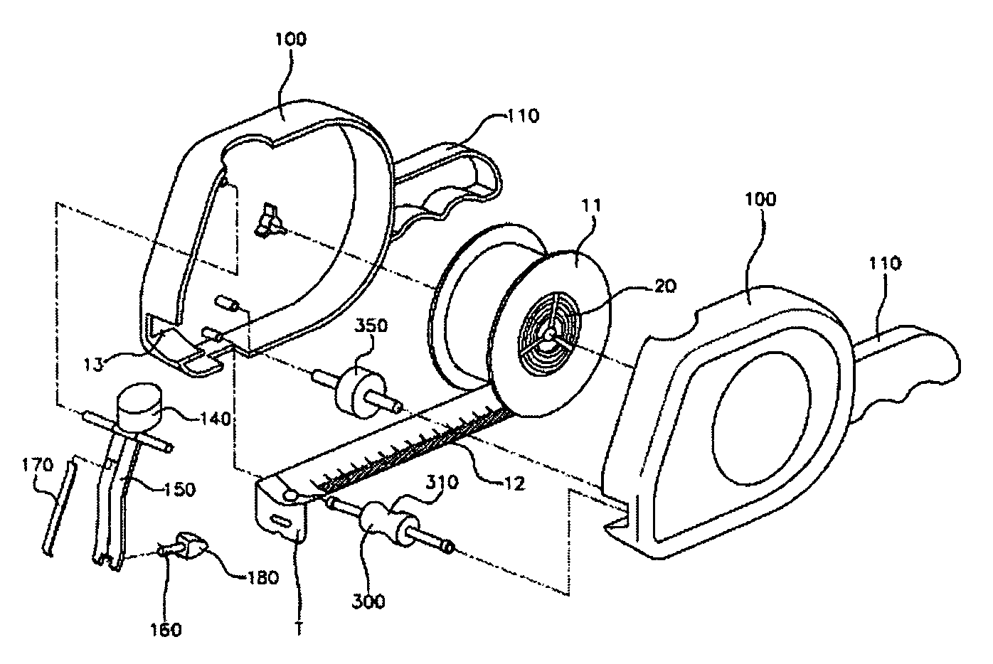
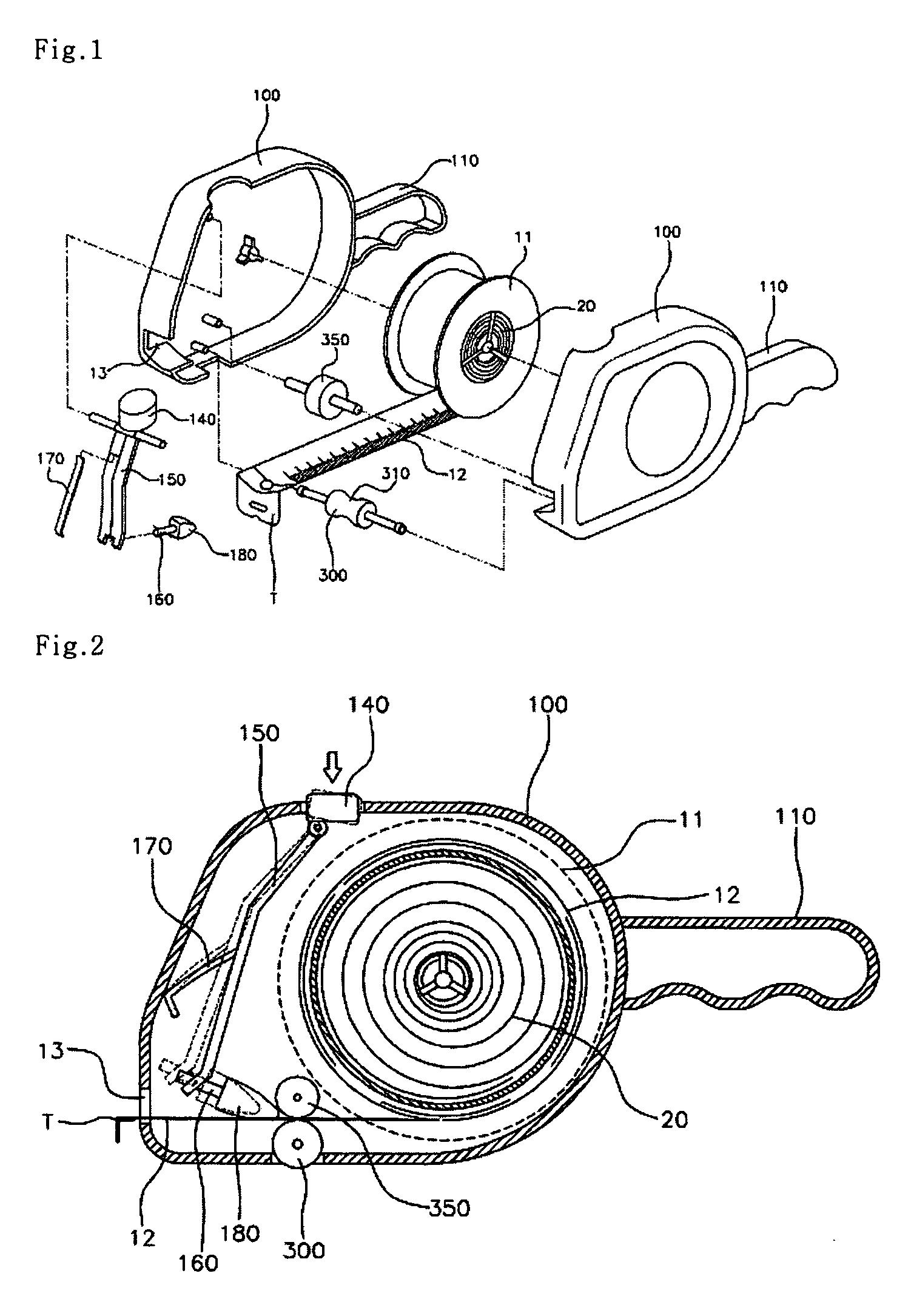
[0030]FIG. 1 is an exploded perspective view of a tape measure with an automatic blade extension mechanism, according to the present invention, and FIG. 2 is a sectional view of the tape measure of FIG. 1.
[0031] As shown in FIGS. 1 and 2, the tape measure with the automatic blade extension mechanism, according to the first embodiment of the present invention, includes a housing 100. A slot 13 is formed at a lower position on a surface of the housing 100. A bobbin 11 is rotatably installed in the housing 100. Further, a blade 12 is wound around the bobbin 11 in a coil, and is pulled out through the slot 13.
[0032] A plate spring 20 is provided in the bobbin 11 and wound in a coil while an end of the plate spring 20 is secured to a rotating shaft. When the blade 12 wound around the bobbin 11 is pulled and released, the blade 12 is automatically wound around the bobbin 11 by the elastic force of the plate spring 20.
[0033] Further, a handle 110 is provided on an outer surface of the ho...
second embodiment
[0041] Like the first power transmission unit 500 of the second embodiment, it is possible to extend the blade 12 from the housing 100, even when the housing 100 is moved backwards, by appropriately adjusting the gear number of the second power transmission unit 500. The second power transmission unit 500 of this embodiment may be variously changed.
[0042] Preferably, a blade locking unit is provided at a predetermined position on the housing 100 to lock the extended blade 12.
[0043] An earlier patent disclosure dealing with the blade locking unit of this invention is found in Korean Laid-Open Publication No. 2003-0065290 which was filed by the inventor of this invention. The publication is incorporated into this invention. The construction of the blade locking unit common to both this invention and the prior art will not be described in detail herein.
[0044] The blade locking unit includes a locking lever and a compression piece. The locking lever is mounted to a predetermined posit...
fourth embodiment
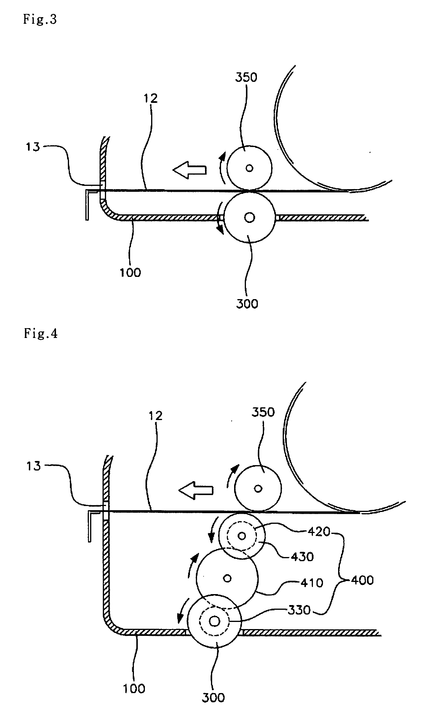
[0048]FIG. 7 shows a tape measure with an automatic blade extension mechanism, according to the present invention. As shown in the drawing, a slot 120 is provided on a side surface of a housing 100 such that a rotating shaft of a ground contact roller 300 moves forwards and backwards. The tape measure is provided with a first power transmission unit. The first power transmission unit transmits the rotating force of the ground contact roller 300 to extend the blade 12 from the housing 100, when the rotating shaft of the ground contact roller 300 reaches the front or rear edge of the slot 120.
[0049] The fourth embodiment of this invention is similar to the second embodiment in that the first power transmission unit 400 is provided between the ground contact roller 300 and the blade 12 to transmit the rotating force from the ground contact roller 300 to the blade 12. The first power transmission unit according to the fourth embodiment includes a first gear 330, a sixth gear 440, a fron...
PUM
 Abstract
Description
Claims
Application Information
 - Generate Ideas
- Intellectual Property
- Life Sciences
- Materials
- Tech Scout
- Unparalleled Data Quality
- Higher Quality Content
- 60% Fewer Hallucinations
Browse by: Latest US Patents, China's latest patents, Technical Efficacy Thesaurus, Application Domain, Technology Topic, Popular Technical Reports.
© 2025 PatSnap. All rights reserved.Legal|Privacy policy|Modern Slavery Act Transparency Statement|Sitemap|About US| Contact US: help@patsnap.com