Conductive plastic fuel filter funnel having improved flow rate and separation

Inactive Publication Date: 2006-05-11
SHURHOLD INDS
View PDF13 Cites 9 Cited by
  • Summary
  • Abstract
  • Description
  • Claims
  • Application Information

AI Technical Summary

Benefits of technology

[0006] The present invention is a conductive plastic fuel filter funnel which is capable of handling relatively large fuel flow rates, while, at the same time filtering water and dirt from fuels, such as gasoline and kerosene. The container of the present invention is made of an electrically conductive plastic, and it includes highly effective filter means which prevent water or dirt from passing,

Problems solved by technology

In the past there were a number of problems with gravity operated (e.g., “passive”) fuel filter funnels.
In particular, the fuel filter funnels of the prior art, such as the one described in U.S. Pat. No. 4,430,222 entitled WATER SHEDDING DEVICE which issued on Feb. 7, 1984 to R. E. Walker, were limited as to the rate of fuel flow of which they provided, their ability to separate water from the fuel, and in their ability to deal with issues of static electricity build up.
In addition, due to the location of fuel tank filler openings in a variety of vehicles, generators, and other equipment which uses fuel, there were problems with the known fuel filler funnels of the prior art.
Attempts to modify the previously known fuel filter funnels, particularly by increasing their size in an attempt to increase their flow rate, resulted in a breakdown of their ability to separate water from fuel.
Another known problem of the fuel f

Method used


Image

  • Conductive plastic fuel filter funnel having improved flow rate and separation
  • Conductive plastic fuel filter funnel having improved flow rate and separation
  • Conductive plastic fuel filter funnel having improved flow rate and separation

Examples


Embodiment Construction

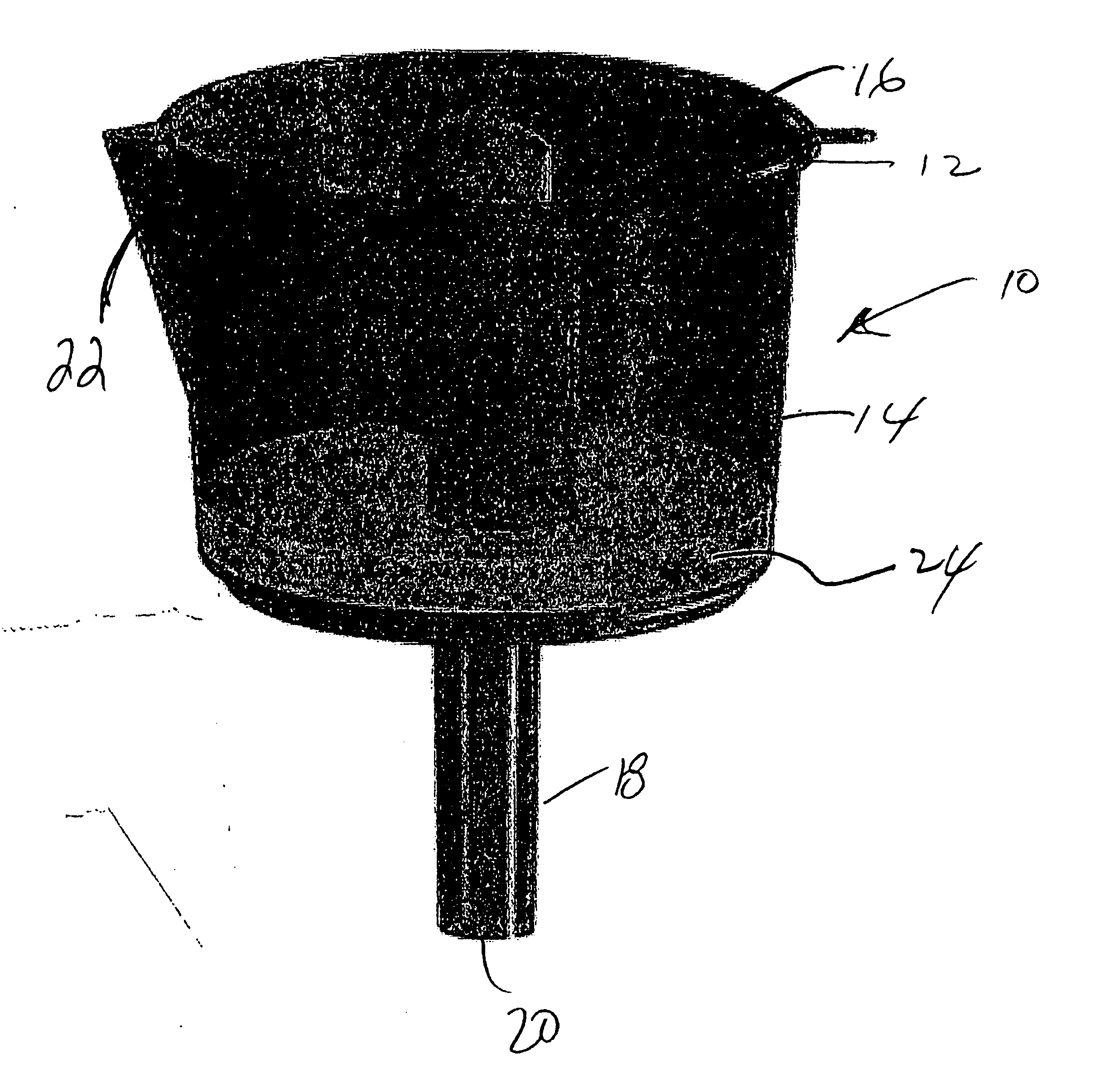
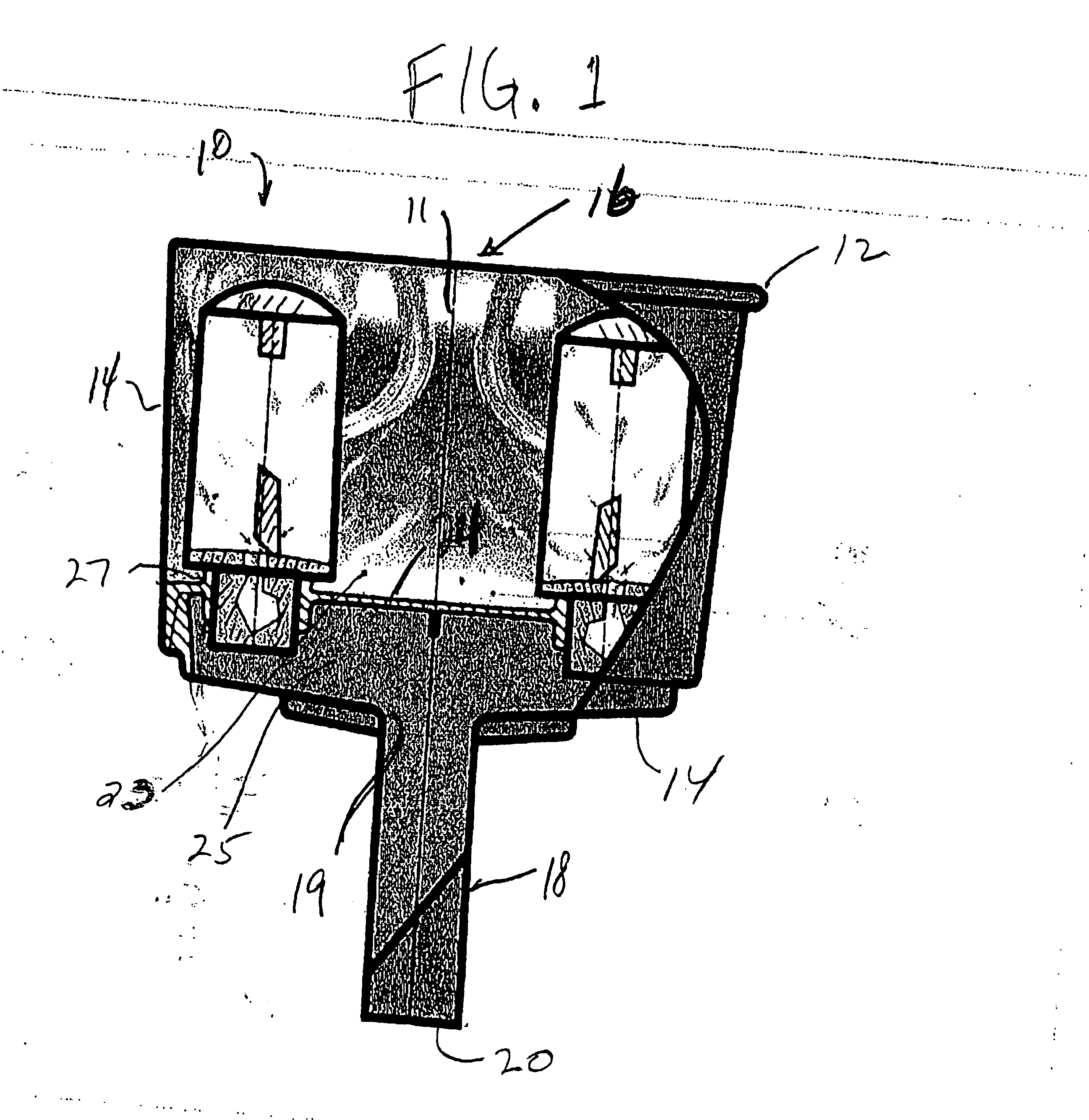
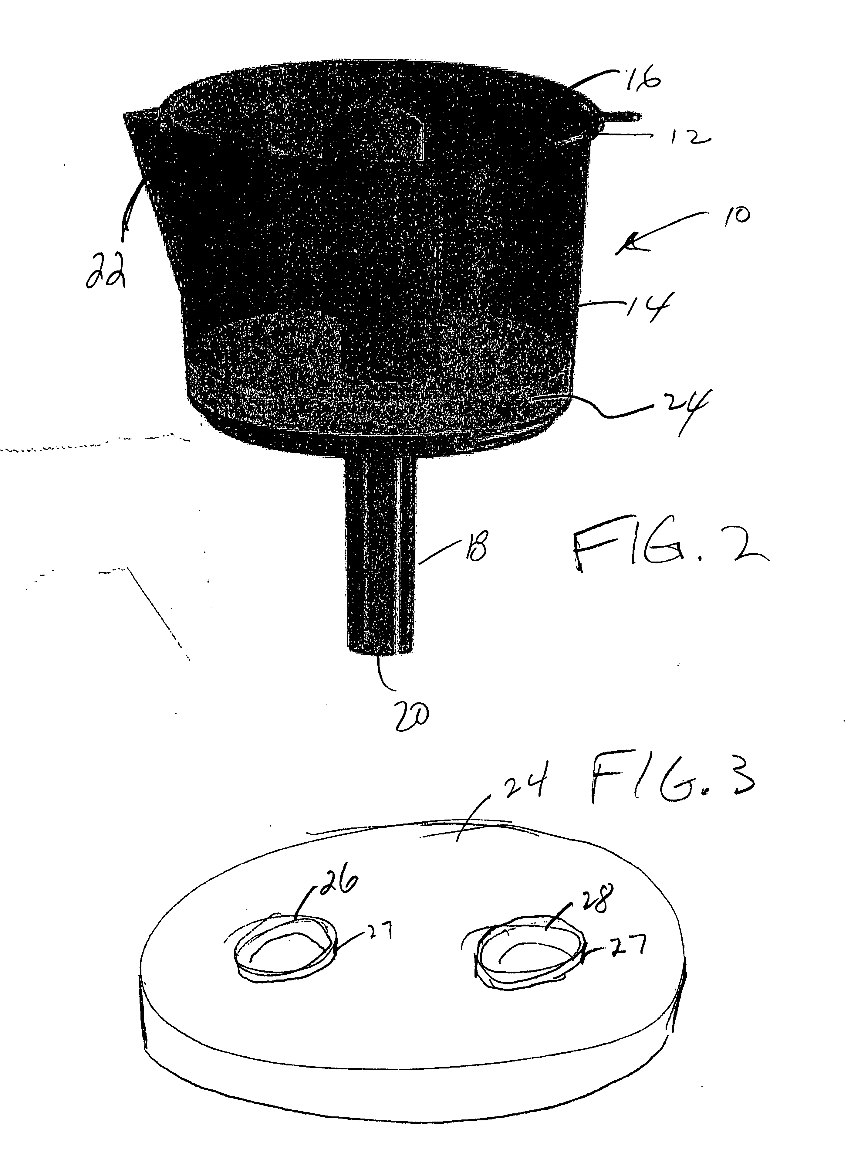
[0014] Referring first to FIGS. 1-4, in the preferred embodiment of the invention, the fuel filter funnel 10 includes a substantially cylindrical upper bowl 11 which slopes inward somewhat from the top 12 to the base 14. The upper bowl has a relatively wide opening 16, which is approximately 8 inches in diameter in the preferred embodiment of the invention. The spout 18, which is about 4 inches in length in the preferred embodiment 10, and which has a diameter of about 1⅜ inches at its lower end 20 communicates with the upper bowl through a relatively smaller opening 19 formed through the floor of the upper bowl. The fuel filter funnel 10 is preferably made of an electro-conductive polypropylene plastic which allows the funnel 10 to be grounded or bonded to fuel source, to eliminate static discharges which could lead to explosions.

[0015] As shown in FIGS. 2 and 4, the fuel filter funnel 10 preferably includes a pouring spout 22 formed in its upper portion, the purpose of which is t...


PUM

PropertyMeasurementUnit
Lengthaaaaaaaaaa
Diameteraaaaaaaaaa
Diameteraaaaaaaaaa

Abstract

The fuel filter funnel is made of a conductive plastic. It has an upper portion which includes a round plastic base having a pair of openings into which a pair filters are press fit. The filters have Teflon coated, stainless steel mesh, which is housed in plastic skeletal structures. Having multiple filters permits a flow rate of at least 15 gallons per minute. In operation, the plastic base creates a false floor, which helps in fuel flow, while the lower, cylindrical portion of the filter housing, combined with the lip formed around the openings in the plastic base form a “sump” into which water and impurities in the fuel are directed. The lack of pressurization, combined with the non-stick Teflon coating, prevents contaminants from being forced into the filter media, while the plastic parts of the remaining portions prevent contaminants from sticking, as well, thereby making for a unit which requires neither cleaning nor replacement parts. The spout at the bottom of the funnel is shaped and sized so that standard PVC pipe can be fitted to the funnel in order to direct the flow of clean fuel, as desired.

Description

BACKGROUND OF THE INVENTION [0001] The present invention relates to a fuel filter funnel. In particular, the invention relates to an improved fuel filter funnel which has been adapted for use with a variety of fuels, has a high flow rate, is able to separate dirt and water from fuel, and which has been adapted for a variety of applications. [0002] Fuel filter funnels are used to fill fuel tanks, such as those on motor vehicles while, at the same time, removing any contaminants from the fuel. In particular, such filter funnels are used to separate water and / or dirt from fuels such as gasoline, diesel fuel, and kerosene. [0003] In the past there were a number of problems with gravity operated (e.g., “passive”) fuel filter funnels. In particular, the fuel filter funnels of the prior art, such as the one described in U.S. Pat. No. 4,430,222 entitled WATER SHEDDING DEVICE which issued on Feb. 7, 1984 to R. E. Walker, were limited as to the rate of fuel flow of which they provided, their ...

Claims


Application Information

Patent Timeline
IPC IPC(8): B01D24/38
CPCB01D29/085
Inventor PATCH, ROGER
Owner SHURHOLD INDS
Why Eureka
Try Eureka