Liquid crystal display device

a liquid crystal display and display device technology, applied in the direction of identification means, instruments, computing, etc., can solve the problems of insufficient control of the voltage being applied to the sub-pixel electrode at the predetermined ratio, and insufficient improvement of the viewing angle dependence of the characteristic of a normally black mode liquid crystal display device. , to achieve the effect of improving the characteristic o

Active Publication Date: 2006-05-11
SHARP KK
View PDF42 Cites 68 Cited by
  • Summary
  • Abstract
  • Description
  • Claims
  • Application Information

AI Technical Summary

Benefits of technology

[0014] In order to overcome the problems described above, preferred embodiments of the present invention provide a pixel-divided liquid crystal display device having significantly increased controllability of voltages to be applied to sub-pixels and also provide a novel pixel dividing technique that greatly improves the γ characteristic of a normally black mode liquid crystal display device.

Problems solved by technology

However, the display performance (e.g., the viewing angle characteristic, in particular) thereof is not fully satisfactory.
Thus, it is difficult to control the voltages being applied to the sub-pixel electrodes at the predetermined ratio.
The present inventors discovered and confirmed via experiments that the application of such voltages effectively improved the viewing angle characteristic of a liquid crystal display device operating in a display mode that shows heavy viewing angle dependence responsive to relatively high voltages applied (e.g., a normally white mode TN mode liquid crystal display device) but could not improve the viewing angle dependence of the γ characteristic of a normally black mode liquid crystal display device sufficiently.
Thus, this problem is particularly non-negligible when an image such as a still picture is displayed or when a televised video is displayed.
On the other hand, when the IPS mode is adopted, it is more difficult to manufacture panels showing a sufficiently high contrast ratio to the front viewer than the MVA mode or ASM mode.

Method used


Image

  • Liquid crystal display device
  • Liquid crystal display device
  • Liquid crystal display device

Examples


Embodiment Construction

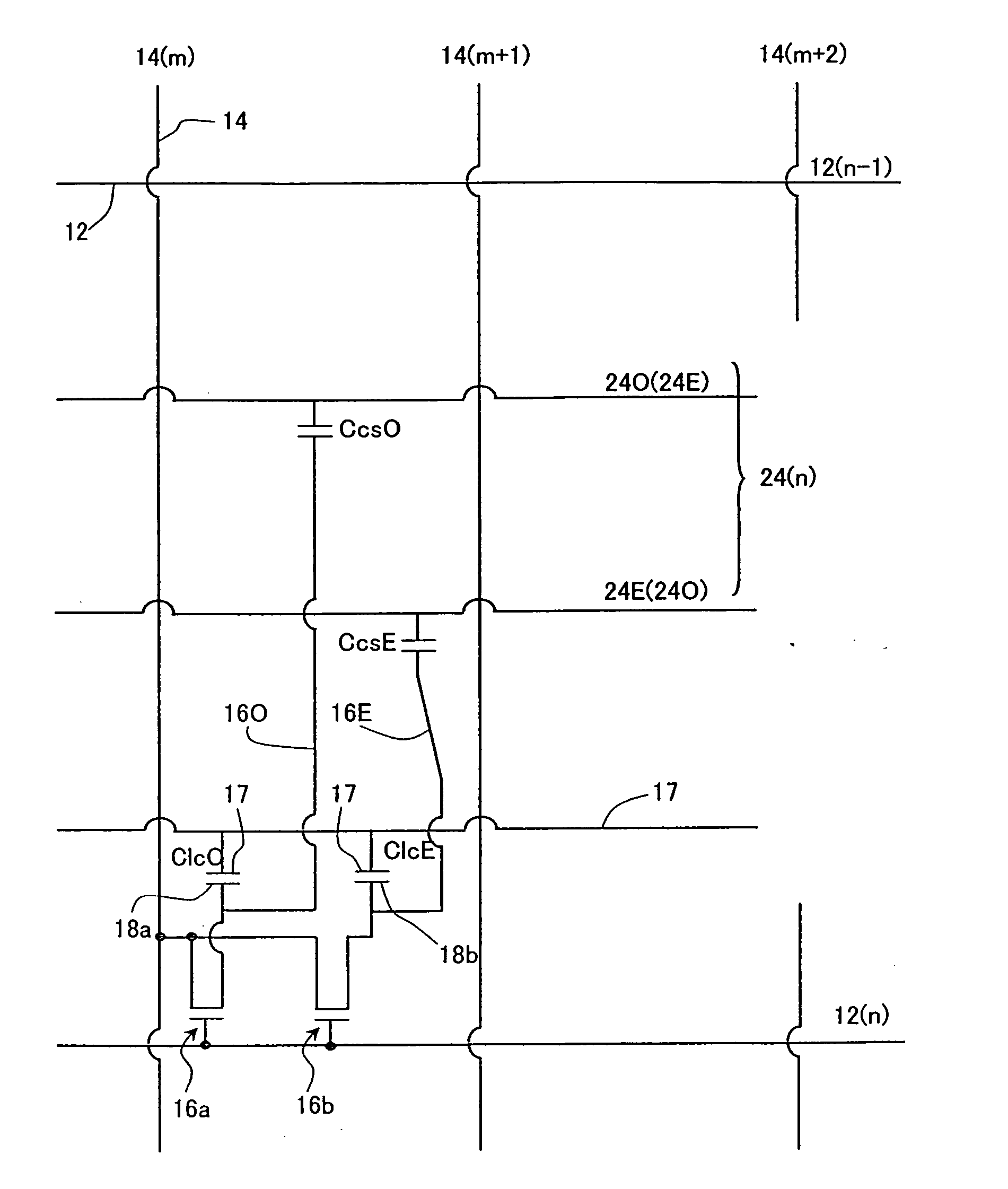
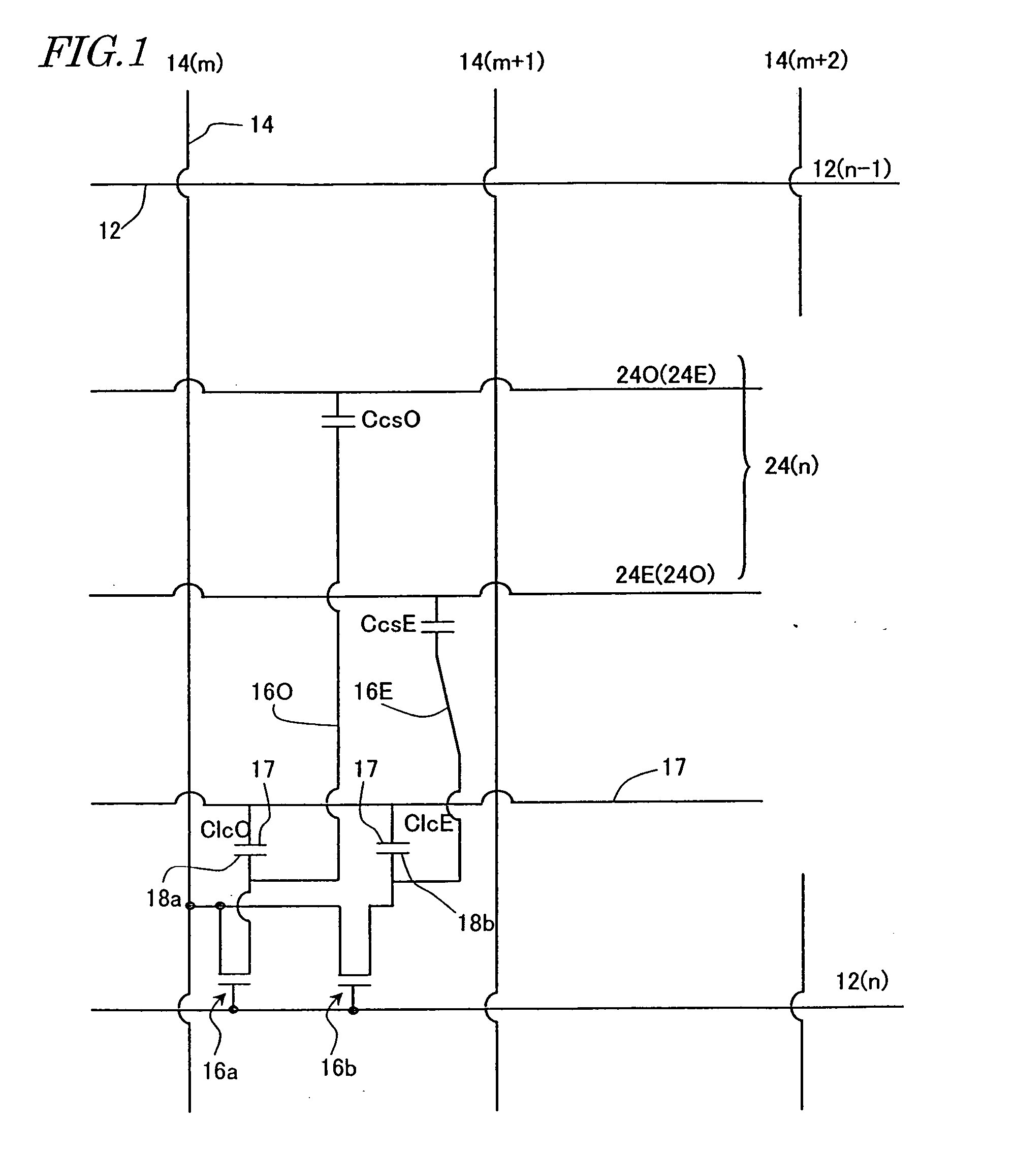
[0051] In a liquid crystal display device according to a preferred embodiment of the present invention, each pixel preferably includes a first sub-pixel and a second sub-pixel, through which mutually different voltages are applicable to the liquid crystal layer. Each of the first and second sub-pixels preferably includes a liquid crystal capacitor and a storage capacitor, which is electrically connected to the liquid crystal capacitor. The liquid crystal capacitor is preferably defined by a counter electrode and a sub-pixel electrode that faces the counter electrode by way of the liquid crystal layer. The storage capacitor is preferably defined by a storage capacitor electrode, an insulating layer, and a storage capacitor counter electrode. The storage capacitor electrode is preferably electrically connected to the sub-pixel electrode. The storage capacitor counter electrode preferably faces the storage capacitor electrode by way of the insulating layer. The counter electrode is pre...


PUM

PropertyMeasurementUnit
anglesaaaaaaaaaa
azimuth anglesaaaaaaaaaa
azimuth angleaaaaaaaaaa

Abstract

In an active-matrix liquid crystal display device, each of multiple pixels includes a first sub-pixel and a second sub-pixel, through which different voltages are applicable to a portion of the liquid crystal layer. Each of the first and second sub-pixels includes a liquid crystal capacitor defined by a counter electrode and a sub-pixel electrode that faces the counter electrode by way of the liquid crystal layer, and a storage capacitor defined by a storage capacitor electrode, an insulating layer, and a storage capacitor counter electrode. The storage capacitor electrode is electrically connected to the sub-pixel electrode, and the storage capacitor counter electrode faces the storage capacitor electrode by way of the insulating layer. The counter electrode is shared by the first and second sub-pixels and the storage capacitor counter electrodes of the first and second sub-pixels are electrically independent of each other.

Description

[0001] This application is a Continuation Application of U.S. patent application Ser. No. 10 / 460,372 filed Jun. 13, 2003, currently pending.BACKGROUND OF THE INVENTION [0002] 1. Field of the Invention [0003] The present invention relates to a liquid crystal display device and more particularly, the present invention relates to a liquid crystal display device of a pixel-divided type. [0004] 2. Description of the Related Art [0005] A liquid crystal display (LCD) is a flat-panel display that has a number of advantageous features including high resolution, drastically reduced thickness and weight, and low power dissipation. The LCD market has been rapidly expanding recently as a result of tremendous improvements in its display performance, significant increases in its productivity, and a noticeable rise in its cost effectiveness over competing technologies. [0006] A twisted-nematic (TN) mode liquid crystal display device, which used to be used extensively in the past, is subjected to an...

Claims


Application Information

Patent Timeline
Patent Type & Authority Applications(United States)
IPC IPC(8): G09G3/36G02F1/1337G02F1/133G02F1/1343G02F1/1362G02F1/1368G09F9/30G09G3/20
CPCG02F1/136213G02F2001/134345G09G3/3614G09G3/3648G09G2300/0443G09G2300/0447G09G2300/0876G09G2320/028G02F1/134345G02F1/133
Inventor TAKEUCHI, MASANORINAGASHIMA, NOBUYOSHIKONDO, NAOFUMI
Owner SHARP KK
Why Eureka
Try Eureka