Exercise device

a technology of exercise device and frame, which is applied in the direction of muscle exercise device, gymnastic exercise, sport apparatus, etc., can solve the problems of user's ability to change the resistance level, limited range of positions of the frame, bench, cable and pulley system,

Active Publication Date: 2006-05-11
NAUTILUS INC
View PDF83 Cites 79 Cited by
  • Summary
  • Abstract
  • Description
  • Claims
  • Application Information

AI Technical Summary

Benefits of technology

[0008] Aspects of the present invention involve an exercise device configurable to allow a user to perform various exercises. The exercise devices described and depicted herein include an adjustable bench assembly connected with a frame supporting adjustable arm and cable-pulley assemblies providing a user interface with a resistance system. The exercise devices can include various types of resistance systems and/or resistance packs. Some embodiments of the exercise devices also include a resistance system with a transmission supporting a plurality of resistance packs. The transmission allows a user to convenient

Problems solved by technology

However, on some of these exercise devices, the range of positions for the frame, bench, and cable and pulley system may be limited.
Thus, these exercise devices confine the range of positions available for performing various exercises.
In addition, many of the exe

Method used


Image

  • Exercise device
  • Exercise device
  • Exercise device

Examples


first embodiment

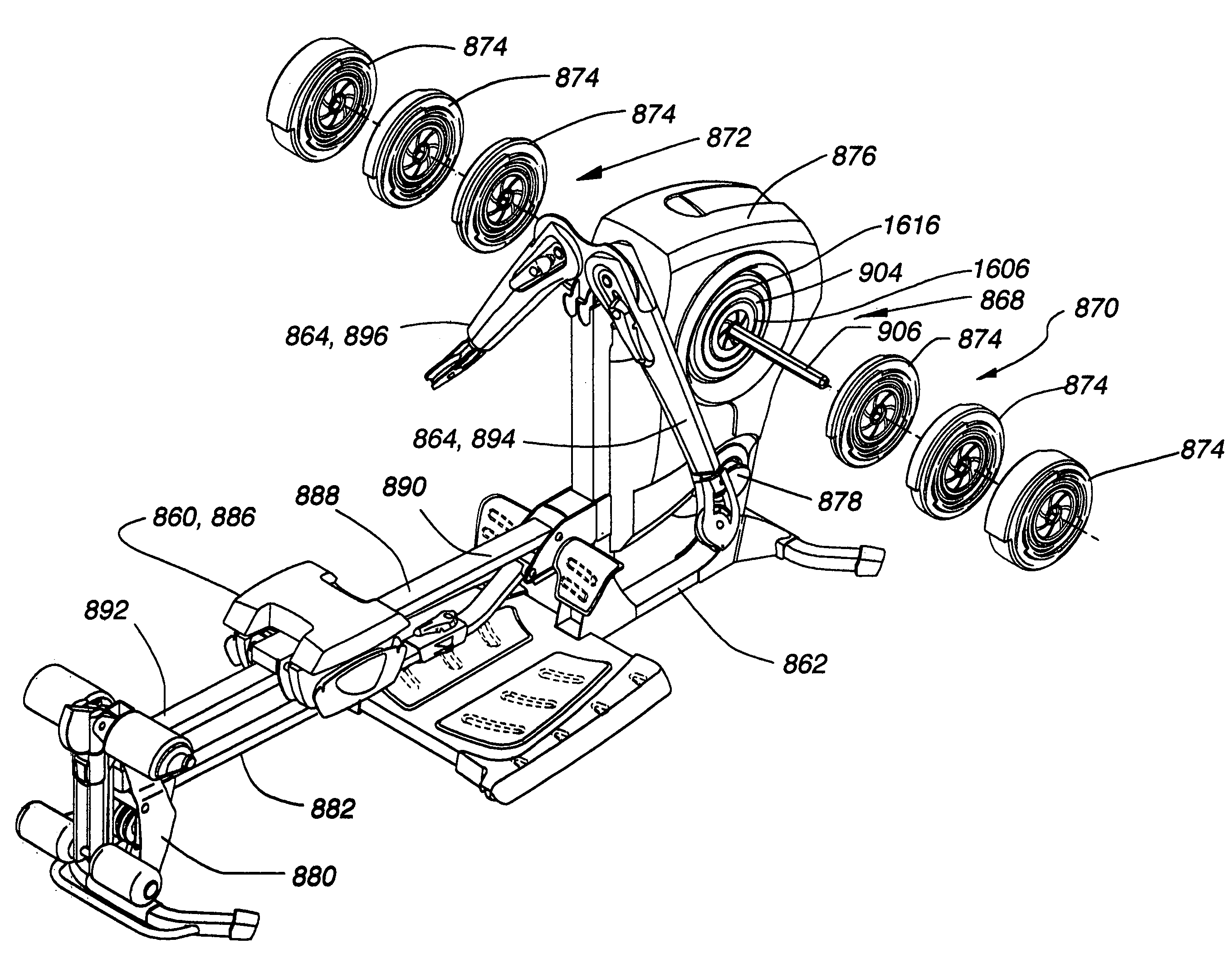
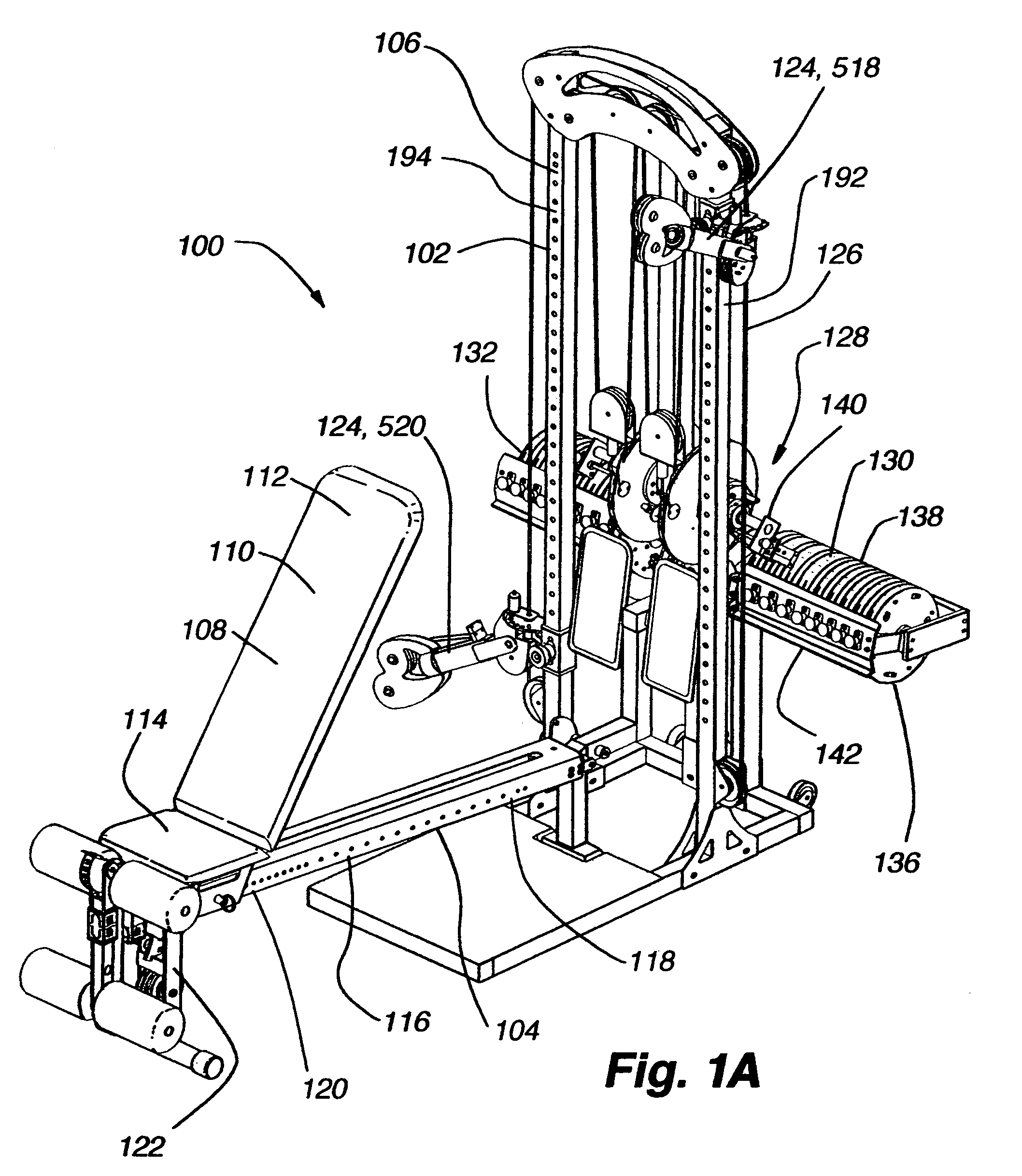
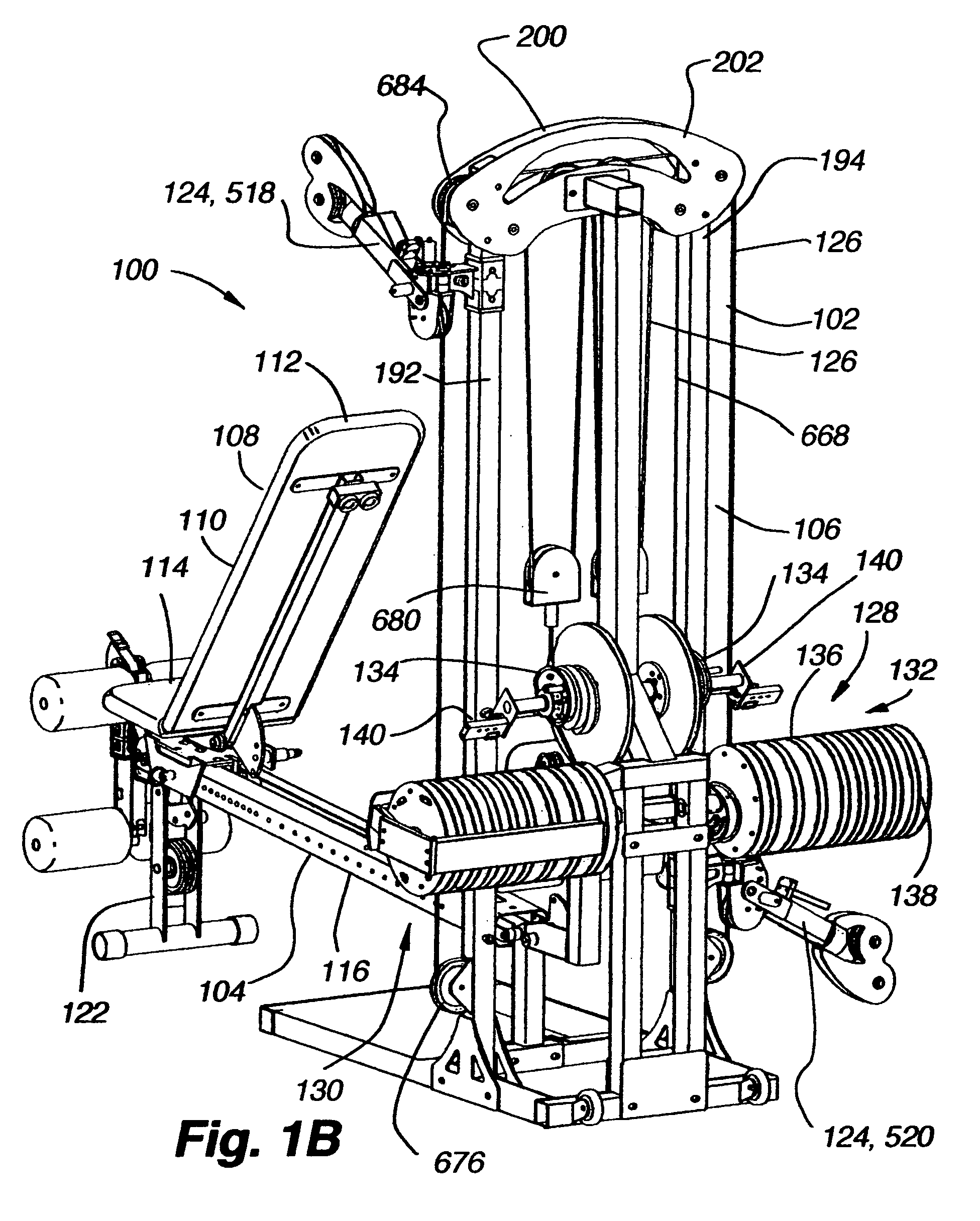
[0182] an exercise device 100 conforming to aspects of the present invention is shown in FIGS. 1A-1D. A frame 102 provides structural support for the exercise device 100. It is to be appreciated that the frame can take on numerous different configurations depending on particular arrangements and combinations of the exercise device. Some particular frame arrangements are shown and discussed herein with reference to a bench frame portion 104 and a main frame portion 106. The bench frame 104 includes an arrangement of frame members for supporting a seat or bench assembly 108 and various user interface components. As discussed in more detail below, the bench assembly 108 can be adjustable and can include a bench 110 with a pivoting back support 112 and an adjustable bench seat 114. In addition, the bench frame 104 can include a seat rail 116 with a first end portion 118 pivotally connected with the main frame 106 and a second end portion 120 supported by a forward bench support 122. As ...

second embodiment

[0238] the multi-axis release mechanism 522′ is shown in FIG. 13B. The second embodiment 522′ includes a handle 650 connected with an arm slider member 652, as opposed to the lever member 602 described above with reference to the first embodiment 522, to operate the first and second pop-pins 578, 594. More particularly, the arm slider member 652 defines a hollow cross section that is adapted to receive the arm member 526 such that the slider member can slide back and forth along the length of the arm member. The handle 650 defines a substantially square-shaped loop that surrounds the outer periphery of the arm slider member 652 and is connected with two opposing sides of the slider member. The second ends 636, 648 of the first and second cables 610, 612 are connected with a cable connection plate 654 mounted on a top side 656 of the arm slider member 652.

[0239] To operate the second embodiment of the multi-axis release mechanism 522′, a user applies a force to the handle 650 to move...

third embodiment

[0240]FIG. 13C illustrates a multi-axis release mechanism 522″ that is substantially similar to the second embodiment 522′. However, the third embodiment 522″ includes a handle post 658 connected with the top side of this arm slider member 652, as opposed to the handle 650 described above with reference to the second embodiment 522′. As such, a user applies a force to the handle post 658 to move the arm slider member 652 and operate the first and second pop-pins 578, 594.

[0241] With reference to FIGS. 2A-2H, the following provides a brief description of some of the various exercises that can be performed on the exercise device 100 as well as operation of various component on the exercise device in light of the previously described structural details.

[0242] As shown in FIG. 2A, the exercise device 100 is configured for leg extension exercises. The back support 112 on the bench frame 104 is locked in an upright position relative to the bench seat 114 with the back support pop-pin 410...


PUM


Abstract

Aspects of the present invention involve an exercise device configurable to allow a user to perform various exercises. The exercise devices include an adjustable bench assembly connected with a frame supporting adjustable arm and cable-pulley assemblies providing a user interface with a resistance system. In some embodiments of the invention, the adjustable bench assembly includes a bench seat and a pivotal back support supported on an adjustable bench frame. The exercise devices also utilize various configurations of adjustable arm assemblies that are selectively positionable for numerous exercises and to suit a user's particular body size and shape. Other embodiments of the exercise devices include a resistance system with a transmission supporting a plurality of resistance packs. The transmission allows a user to conveniently engage any number of resistance packs to change the resistance level for a particular exercise.

Description

CROSS-REFERENCE TO RELATED APPLICATIONS [0001] This application claims the benefit of U.S. Provisional Application No. 60 / 618,131, filed Oct. 12, 2004; U.S. Provisional Application No. 60 / 644,110, filed Jan. 14, 2005; and U.S. Provisional Application No. 60 / 662,808, filed on Mar. 15, 2005, all of which are hereby incorporated by reference herein. [0002] U.S. patent application Ser. No. 29 / 225,514, titled “Exercise Device,” filed on Mar. 15, 2005; U.S. Pat. No. 4,944,511, titled “Adjustable Resilient Reel Exerciser,” filed on Jan. 23, 1989; U.S. Pat. No. 5,209,461, titled “Elastomeric Torsional Spring Having Tangential Spokes With Varying Elastic Response,” filed on Jun. 12, 1992; U.S. Pat. No. 6,126,580, titled “Resistance Exercise Machine With Series Connected Resistance Packs,” filed on Aug. 7, 1998; and U.S. Pat. No. 6,440,044, titled “Resistance Mechanism With Series Connected Resistance Packs,” filed on Aug. 1, 2000, are all hereby incorporated by reference herein.BACKGROUND OF...

Claims


Application Information

Patent Timeline
IPC IPC(8): A63B21/062
CPCA63B21/00047A63B21/045A63B21/154A63B21/155A63B21/156A63B2225/102A63B21/1461A63B21/1484A63B21/1492A63B23/03525A63B23/03566Y10S482/908A63B21/4043A63B21/4031A63B21/4047
Inventor DIBBLE, RYAN R.WARNER, PATRICK A.GOLESH, ERIC D.CHRISTOPHER, BRENT
Owner NAUTILUS INC
Why Eureka
Try Eureka