Locking mechanism for a wind turbine generator

a technology of wind turbine generator and locking mechanism, which is applied in the direction of motors, dynamo-electric machines, engine fuctions, etc., can solve the problems of inefficiency of wind turbine operation, time-consuming and laborious to perform any type of maintenance on any of the elements housed in the nacelle (such as the generator or the gearbox), and the need to maintain or replace the wind turbin

Pending Publication Date: 2022-03-03
VESTAS WIND SYST AS
View PDF5 Cites 0 Cited by
  • Summary
  • Abstract
  • Description
  • Claims
  • Application Information

AI Technical Summary

Benefits of technology

[0024]With the axial locks engaged, axial movements of the rotor relative to the stator and other static parts of the generator are blocked. Engagement of the axial locks is conveniently realised by just placing the removable block against the end shield and engaging the engagement tool of the lock with the engagement feature at the end surface of the rotor. With the axial locks engaged, the rotor is protected against damage during transport of the generator. Further, axially locking the rotor may allow for maint

Problems solved by technology

As a result, it is expected that components of the wind turbine will need to be maintenanced or replaced during its operational lifetime as these components undergo degradation through use.
The nacelle of a wind turbine will often be positioned around 100 metres from the ground, and so to perform any sort of maintenance on any of the elements housed in the nacelle (such as the generator or the gearbox) can require a great deal of time, effort and expertise.
Furthermore, whilst the wind turbine is undergoing maintenance, it will be required to be non-operational and such maintenance time therefore introduces a source of inefficiency to the operation of the wind turbine.
However, the rate of degradation of each of the interna

Method used


Image

  • Locking mechanism for a wind turbine generator
  • Locking mechanism for a wind turbine generator
  • Locking mechanism for a wind turbine generator

Examples


Embodiment Construction

[0048]A specific embodiment of the present invention will now be described in which numerous features will be discussed in detail in order to provide a thorough understanding of the inventive concept as defined in the claims. However, it will be apparent to the skilled person that the invention may be put into effect without the specific details and that in some instances, well known methods, techniques and structures have not been described in detail in order not to obscure the invention unnecessarily.

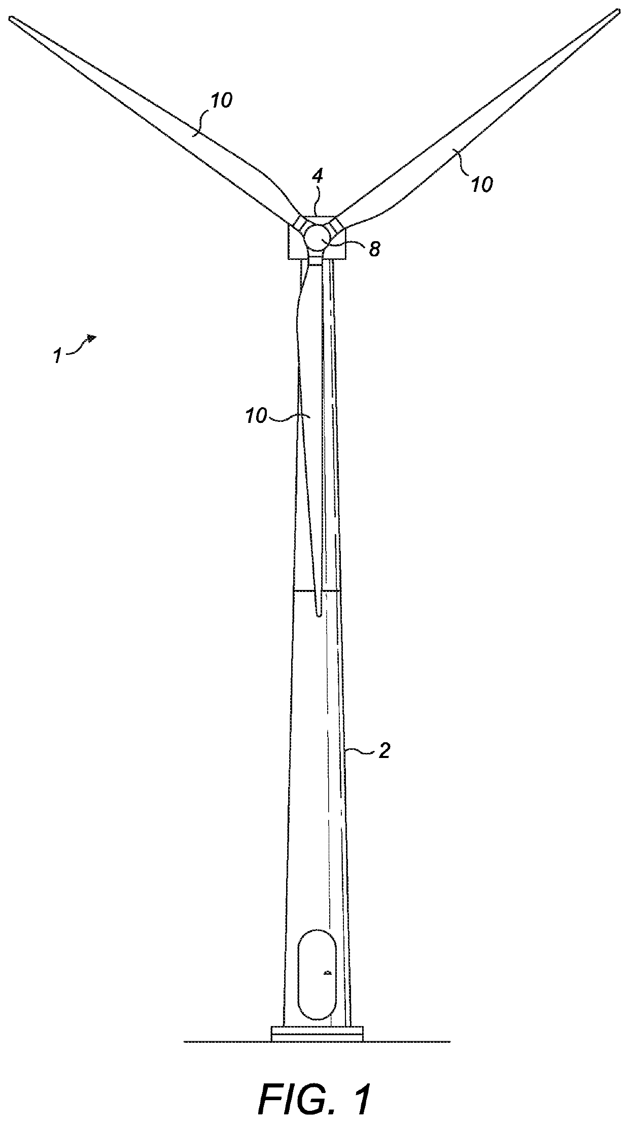
[0049]In order to place the embodiments of the invention in a suitable context, reference will firstly be made to FIG. 1, which illustrates a typical Horizontal Axis Wind Turbine (HAWT) in which a locking mechanism according to an embodiment of the invention may be implemented. Although this particular image depicts an on-shore wind turbine, it will be understood that equivalent features will also be found on off-shore wind turbines. In addition, although the wind turbines are referre...


PUM


Abstract

A generator (24) for a wind turbine (1) comprises a rotor (32) with an axis of rotation, a stator and a radial and/or axial locking mechanism. The radial locking mechanism comprises a plurality of radial locks (60) with a fixed portion (70) coupled to the stator and a movable elongate portion (72) configured to move relative to the fixed portion (70) and radially with respect to the axis of the rotation to lock the stator in a radial direction. The rotor (32) may comprise at least one lock engagement feature (86) arranged at its end surface and an end shield (90) located axially outward and at least partially adjacent the end surface. The end shield (90) comprises at least one opening enabling access to the end surface of the rotor (32). The axial locking mechanism may comprise at least one axial lock (80) comprising a removable block (82) configured to partly cover the at least one opening of the end shield (90) and a rotor engagement tool (84) for engaging the removable block (82) with the at least one lock engagement feature (86).

Description

FIELD OF THE INVENTION[0001]The present invention relates to a generator for a wind turbine and to a rotor assembly for a generator for a wind turbine. Specifically, the present invention relates to a locking mechanism used in a generator and a rotor assembly disposed in a wind turbine.BACKGROUND OF THE INVENTION[0002]Wind turbines convert kinetic energy from the wind into electrical energy, using a large rotor with a number of rotor blades. A typical Horizontal Axis Wind Turbine (HAWT) comprises a tower, a nacelle on top of the tower, a rotor hub mounted to the nacelle and a plurality of wind turbine rotor blades coupled to the rotor hub. Depending on the direction of the wind, the nacelle and rotor blades are turned and directed into an optimal direction by a yaw system for rotating the nacelle and a pitch system for rotating the blades.[0003]The nacelle houses many functional components of the wind turbine, including for example a generator, gearbox, drive train and rotor brake a...

Claims


Application Information

Patent Timeline
IPC IPC(8): F03D80/00H02K7/18
CPCF03D80/00H02K2213/06F05B2260/31H02K7/1838H02K15/0006H02K1/28Y02E10/72
Inventor MANNIK, HENRIK ZAARGÜNDÜZ, MUSTAFAMEINEKAT, ULRICHMONGEAU, PETERJANOTA, MARCIN
Owner VESTAS WIND SYST AS
Why Eureka
Try Eureka