Nozzle assembly housing for vacuum cleaner

a technology for vacuum cleaners and assembly housings, which is applied in the direction of vacuum cleaners, cleaning processes and equipment, chemistry apparatus and processes, etc., can solve the problems of requiring replacement, requiring time-consuming and labor-intensive service of agitator drive belts, and still becoming worn over tim

Inactive Publication Date: 2007-05-22
PANASONIC OF NORTH AMERICA
View PDF3 Cites 0 Cited by
  • Summary
  • Abstract
  • Description
  • Claims
  • Application Information

AI Technical Summary

Benefits of technology

[0008]In accordance with the purposes of the present invention as described herein, a nozzle assembly housing is provided. That nozzle assembly housing includes a first wall, a second wall and an access opening in the first and second walls. A locking tab receiver is provided on the first wall adjacent the access opening. A notch is provided on the second wall adjacent the access opening. Additionally, a removable panel is provided for closing the access opening. The panel includes a locking tab on a first edge mating with the locking tab receiver and a hinge lug on a second edge received in the notch so as to allow pivotal movement of the panel relative to the second wall of the housing.
[0011]Still further, the removable panel also carries a belt guard. In addition, the removable panel includes a finger grip adjacent the locking tab. This finger grip allows the operator to conveniently engage and disengage the locking tab from the locking tab receiver.
[0013]A method of removing a separate, removable panel from the walls of a vacuum cleaner housing is also disclosed. That method includes the steps of (a) depressing a portion of the panel to release a locking tab on the panel from a locking tab receiver on one of the walls; (b) pivoting the panel on a hinge formed between the panel and another of the walls; and (c) removing the panel from the walls. The present invention provides the operator of the vacuum cleaner with the convenience and operating simplicity of a hinged panel for providing access to an agitator drive belt in the housing of the nozzle assembly. Advantageously, this is done while also avoiding any potential inconvenience that might be related to such a panel attached to the nozzle assembly. Specifically, the separate, fully removable hinged panel of the present invention may be positioned at a location remote from the nozzle assembly where it cannot possibly interfere with the belt changing operation.

Problems solved by technology

While advances in belt technology have made significant gains in service life, belts still become worn over time and require replacement.
In many vacuum cleaners, it is difficult and time consuming to service the agitator drive belt.
This can be difficult, time consuming and also very inconvenient.
Further, many individuals are not mechanically inclined and the prospect of such a task leads them to take their vacuum cleaner to professional vacuum cleaner service personnel.
This is often a time consuming and frustrating situation that creates an unfavorable impression upon the consumer.
While very useful and effective for its intended purpose, some individuals find the open access door to be an annoyance or hindrance to belt changing.

Method used


Image

  • Nozzle assembly housing for vacuum cleaner
  • Nozzle assembly housing for vacuum cleaner
  • Nozzle assembly housing for vacuum cleaner

Examples


Embodiment Construction

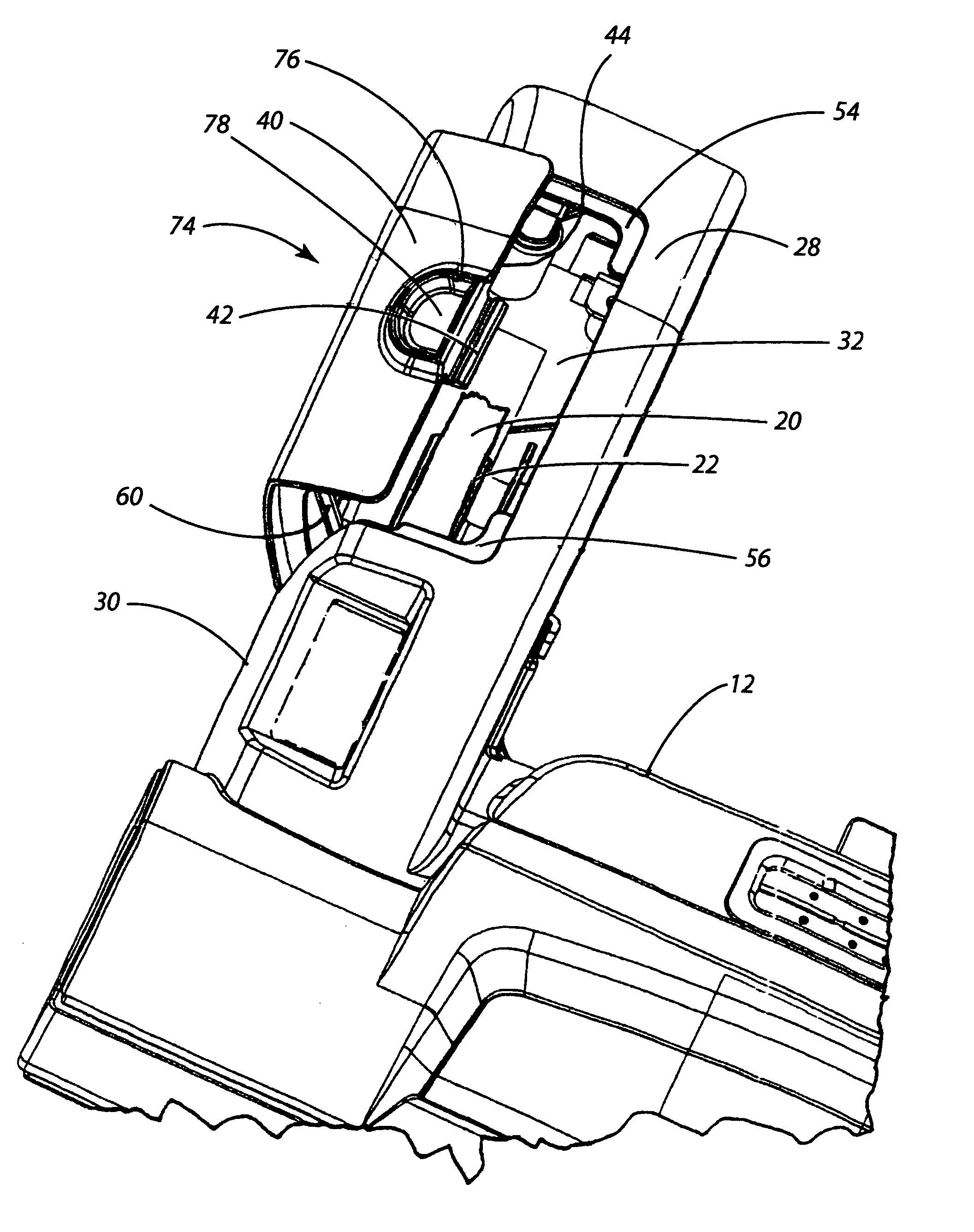
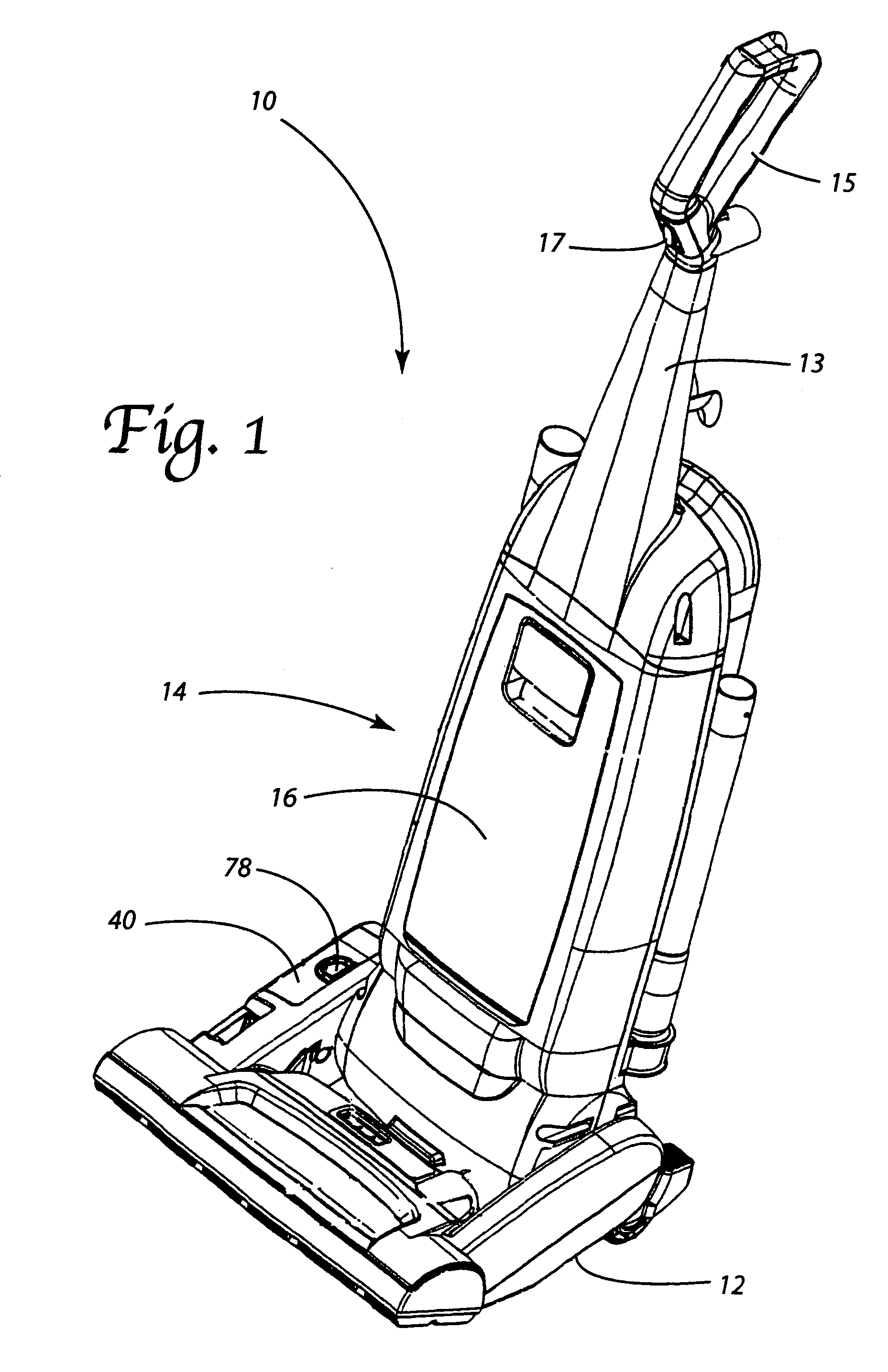
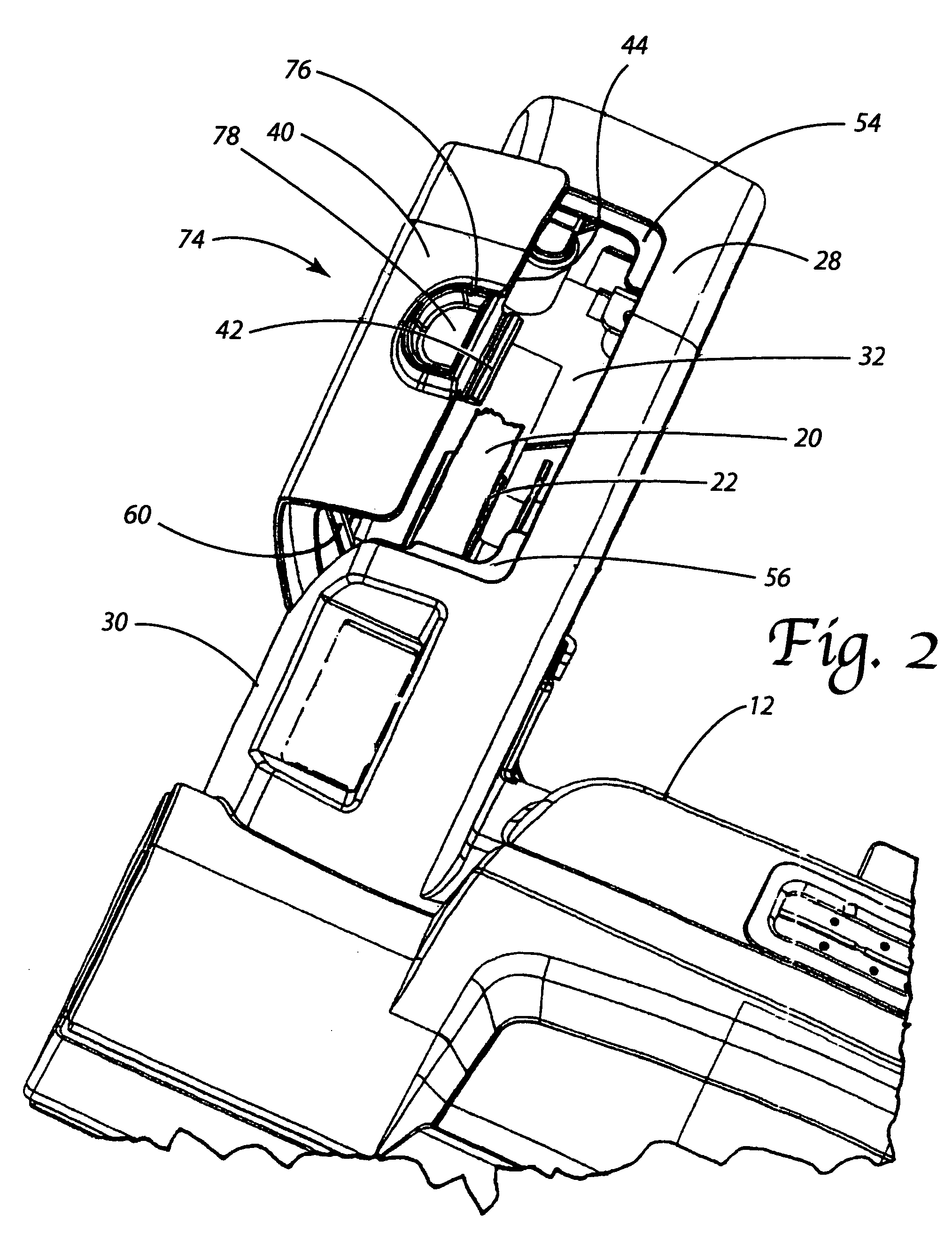
[0024]Reference is now made to FIG. 1 illustrating an upright vacuum cleaner 10 incorporating the nozzle assembly housing 12 of the present invention.

[0025]As illustrated, the vacuum cleaner 10 incorporates a canister assembly housing 14 that is pivotally connected to the nozzle assembly housing 12. The canister assembly housing 14 carries a control handle 13, a hand grip 15 and an on / off actuator switch 17. The canister assembly housing 14 also includes a cavity for holding a dirt cup 16 for collecting dirt and debris. The dirt cup 16 may or may not include structures to produce cyclonic airflow in order to assist in separation of dirt from the airstream as it passes through the vacuum cleaner 10. In the alternative, the cavity may simply house a state-of-the-art bag filter behind an access door or cover instead of a dirt cup.

[0026]The vacuum cleaner 10 also includes a suction generator (not shown) that is mounted in an internal chamber in the canister assembly housing 14. Of cours...


PUM


Abstract

A nozzle assembly housing includes a first wall, a second wall and an access opening in those walls. A locking tab receiver is provided on the first wall adjacent the access opening. A notch is provided on the second wall adjacent the access opening. Finally, a separate, removable panel closes the access opening. That panel includes a locking tab on a first edge that engages the locking tab receiver and a hinge lug on a second edge that is pivotally received in the notch.

Description

[0001]This application claims the benefit of U.S. Patent Application Ser. No. 60 / 490,634 filed on Jul. 28, 2003.TECHNICAL FIELD[0002]The present invention relates generally to the floor care equipment field and, more particularly, to a nozzle assembly housing for a vacuum cleaner or the like incorporating a hinged removable panel and to a related method of securing a removable panel to a housing of a vacuum cleaner.BACKGROUND OF THE INVENTION[0003]Upright, canister and hand-held vacuum cleaners have long been known in the art. Many such vacuum cleaners incorporate one or more rotary agitators. These rotary agitators are equipped with cleaning structures including but not limited to beater bars, wipers, brushes and bristle tufts. As the agitators are rotated relative to the floor being cleaned, these cleaning structures function to beat dirt and debris from the nap of an underlying carpet.[0004]Whether driven by the motor of the suction fan generator or an independent agitator drive ...

Claims


Application Information

Patent Timeline
Patent Type & Authority Patents(United States)
IPC IPC(8): A47L5/10A47L9/00A47L9/02A47L9/04
CPCA47L9/02A47L9/04
Inventor HAFLING, DANIELLE M.MUHLENKAMP, ERIC E.
Owner PANASONIC OF NORTH AMERICA
Why Eureka
Try Eureka