Reservoir for front end loaded infusion device

a technology for infusion devices and reservoirs, which is applied in the field of medical reservoirs, can solve the problems of large space that must be reserved, the reservoir is exposed to unintentional blows, and occupies a lot of space on the infusion device, and achieves convenient operation, convenient operation, and large effective volume of the reservoir.

Inactive Publication Date: 2006-05-11
UNOMEDICAL AS
View PDF56 Cites 14 Cited by
  • Summary
  • Abstract
  • Description
  • Claims
  • Application Information

AI Technical Summary

Benefits of technology

[0013] The object of the invention is achieved by a medical reservoir for a front loaded infusion device comprising a housing, a chamber inside said housing for receiving said reservoir and a drive member, said reservoir comprising a first end; an outlet disposed at said first end; a second open end; an elongate body portion disposed between said first and second ends; and a piston slideable arranged within said elongate body portion and being connectable to said drive member, where said reservoir further comprises sealing means disposed at the first end of said reservoir for sealing / closing said chamber, connecting means for securing the reservoir in the housing, and closable dispensing means. Thereby a very compact closure of the chamber is achieved, further allowing a large effective volume of the reservoir. The reservoir according to the invention thus forms its own closure of a reservoir chamber of an infusion device / pump. Such a reservoir further is much easier to operate by the patient or the medical staff because of the fewer parts when a cap or lid is eliminated.

Problems solved by technology

In such a device, however, ample space must be reserved for means for holding the reservoir, and for means for opening the device, e.g. hinges.
This leaves the reservoir exposed to unintentional blows, which is disadvantageous, since it might damage the reservoir or the device.
The cap taught in this document, however is disadvantages in that it takes up a lot of space on the infusion device as such.
Further the effective length of the reservoir is unintentionally shortened, due to the space that the cap take up.
Further, this device has a rather complex mechanism (the cap) for mounting the reservoir, comprising multiple, expensive components.
When mounting the reservoir in the apparatus, the can must be kept separate from the apparatus itself, with the risk that the cap parts is misplaced or dropped, while handling the reservoir into the pump housing.
If dropped e.g. on the floor the cap may be contaminated.

Method used


Image

  • Reservoir for front end loaded infusion device
  • Reservoir for front end loaded infusion device
  • Reservoir for front end loaded infusion device

Examples


Embodiment Construction

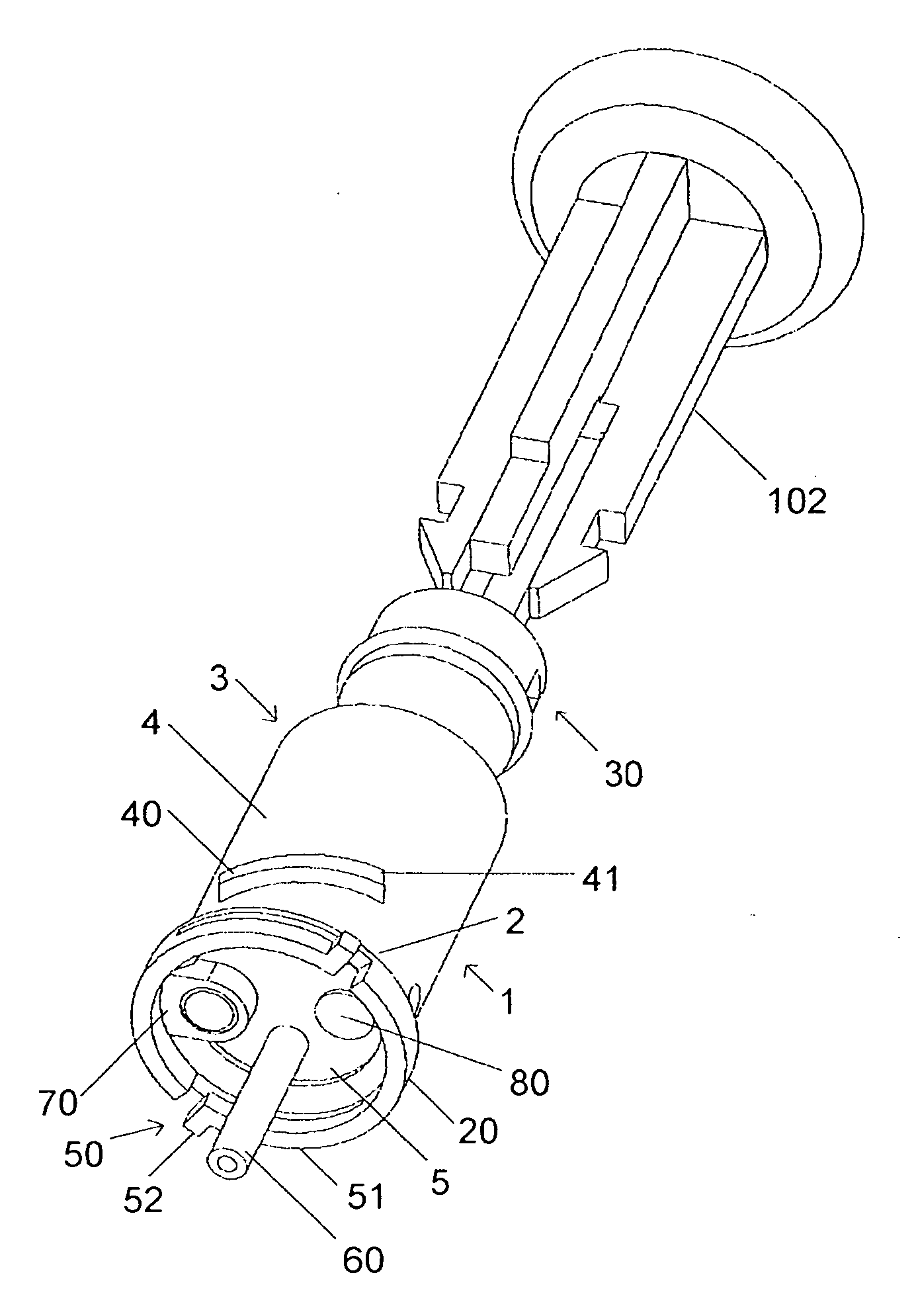
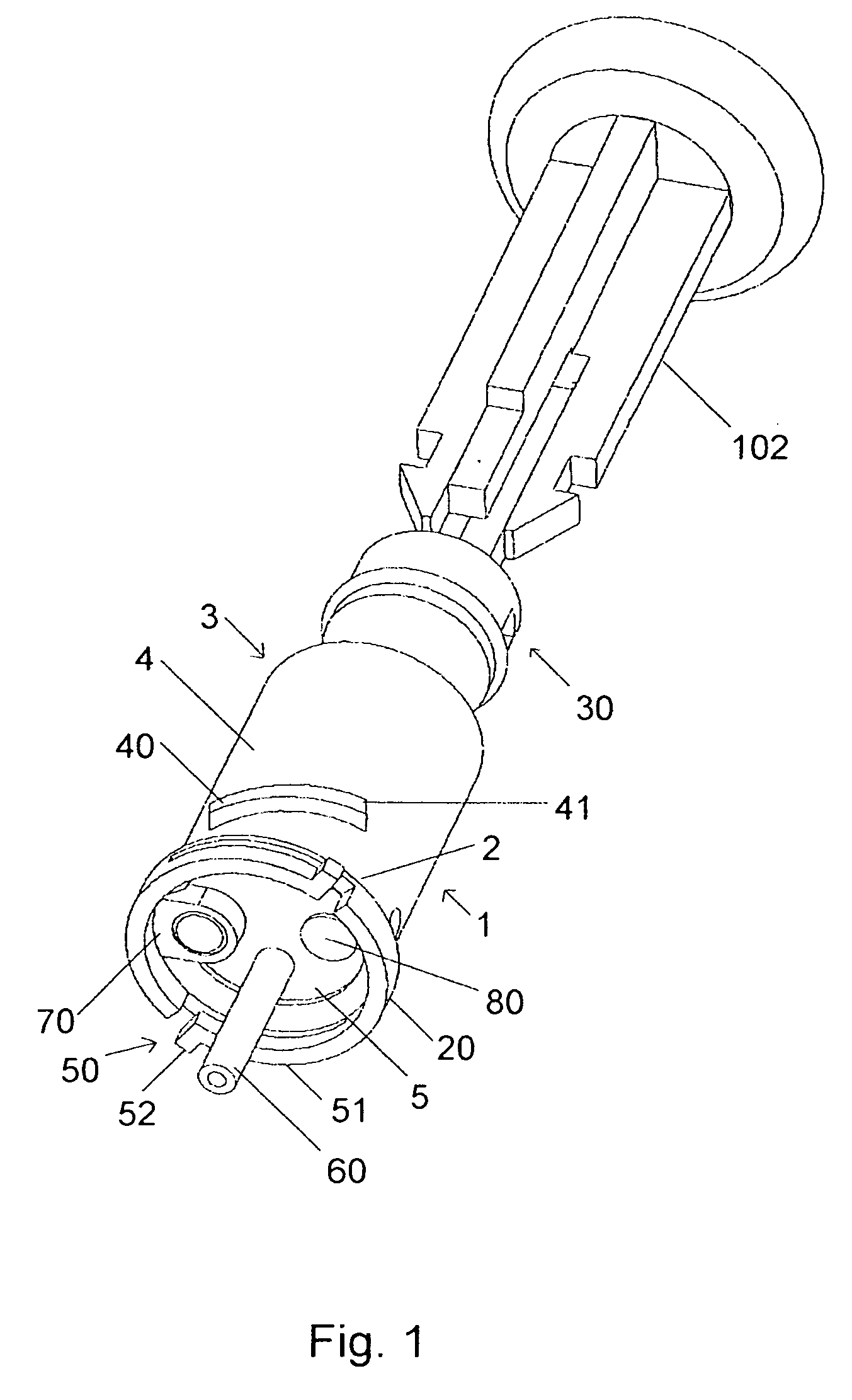
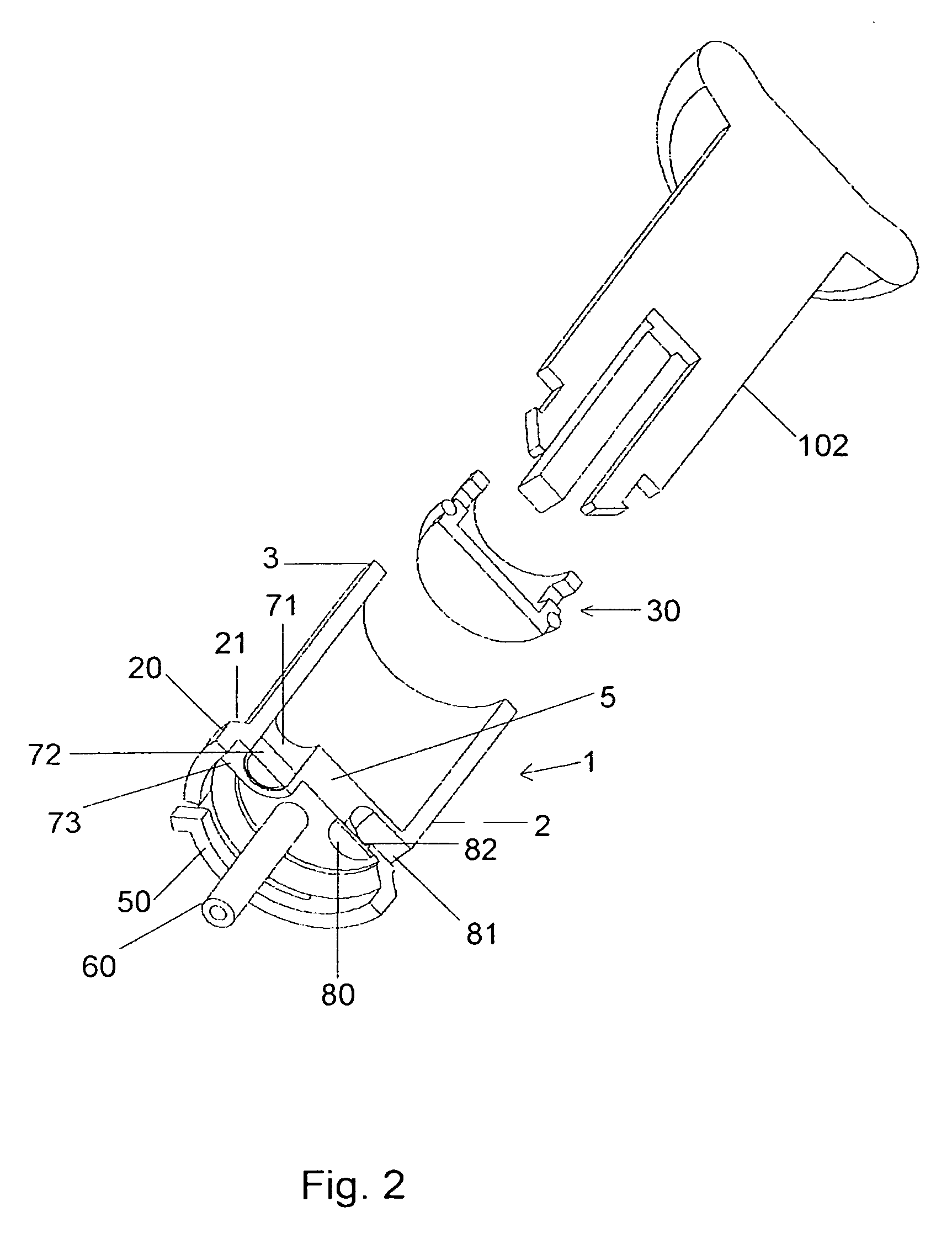
[0020] Referring firstly to FIGS. 1-3, a medical reservoir 1 according to an exemplary embodiment of the invention and a piston rod or drive member 102 is shown. The medical reservoir 1 comprises an elongate body portion 4, having first 2 and second 3 ends, and a piston 30 slideably arranged within said body portion 4. The second end 3 of the body portion 4 is open. The first end is closed e.g. by a wall 5. However, an outlet 6 is disposed therein. The piston 30 comprises sealing means 31 for providing a sealing between the piston 30 and the inner wall of the body portion 4. The body portion 4, the front wall 5 and the piston 30 thus forms a variable volume medical reservoir 1 for containing and dispensing a medical fluid such as e.g. insulin.

[0021] The piston 30 may further comprise means 32 for releasably connecting the piston 30 to a drive member 102. The drive member 102 is preferably a part of a medical injection or infusion device 100, having connection means 132 complementar...


PUM


Abstract

A medical reservoir for a front loaded infusion device including a housing, a chamber inside the housing for receiving the reservoir and a drive member. The reservoir includes a first end; an outlet disposed at the first end, the outlet having closable dispensing means; a second open end; an elongate body portion disposed between the first and second ends; and a piston slideably arranged within the elongate body portion and being connectable to the drive member.

Description

FIELD OF THE INVENTION [0001] The invention relates to the field of medical reservoirs of the type comprising a first end, an outlet disposed at said first end, a second open end, an elongate body portion disposed between said first and second ends, and a piston slideable arranged within said elongate body portion. More particularly, the invention relates to a medical reservoir adapted for an infusion device, adapted for front end loaded medical reservoirs. BACKGROUND [0002] Infusion devices and systems are well known in the medical arts, for use in delivering or dispensing a prescribed medication such as insulin to a patient. Typically such devices comprise a pump housing adapted to receive a replaceable syringe or reservoir containing a prescribed medication for administration to a patient through infusion tubing and an associated catheter or infusion set. [0003] Pump housings typically includes a drive motor connected for driving a reservoir piston to administer the medication to...

Claims


Application Information

Patent Timeline
Patent Type & Authority Applications(United States)
IPC IPC(8): A61M37/00A61M5/145
CPCA61M5/14546A61M5/14566
Inventor MOGENSEN, LASSE WESSELTOFT
Owner UNOMEDICAL AS
Why Eureka
Try Eureka