Tire building drum and tire building method

a tire building and tire technology, applied in the field of tire building drums and tire building methods, can solve the problems of deteriorating accuracy of relative positions between the carcass band or green case and the belt/tread band, failing to solve the above problem, and complicated steps

Inactive Publication Date: 2006-05-18
BRIDGESTONE CORP
View PDF23 Cites 47 Cited by
  • Summary
  • Abstract
  • Description
  • Claims
  • Application Information

AI Technical Summary

Benefits of technology

[0085] With such a tire building method, there is controlled an internal pressure of the center bladder or a spacing between the right and left bead lock means by detecting a load of the motor for driving the sleeve reciprocative driving means as a property alternative to a resistance force upon radially expanding the core body, thereby allowing a smooth radial expansion of the core body to be further ensured.

Problems solved by technology

However, in such a conventional method, the belt / tread band is once detached from the belt / tread forming drum, gripped from radially outside, moved to the shaping drum, and this gripping is released there so as to move the belt / tread band onto the shaping drum, with the result that the steps are made complicated and the tread band is gripped and released many times, thereby causing a problem of a deteriorated accuracy of relative positions between the carcass band or green case and the belt / tread band.
This fails to attain a relative positional relationship between the assembled tire component members and bead cores with high accuracy, thereby still failing to solve the above problem in this point.

Method used


Image

  • Tire building drum and tire building method
  • Tire building drum and tire building method
  • Tire building drum and tire building method

Examples


first embodiment

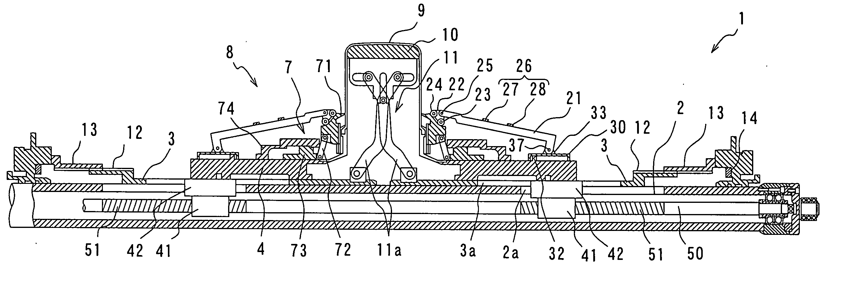
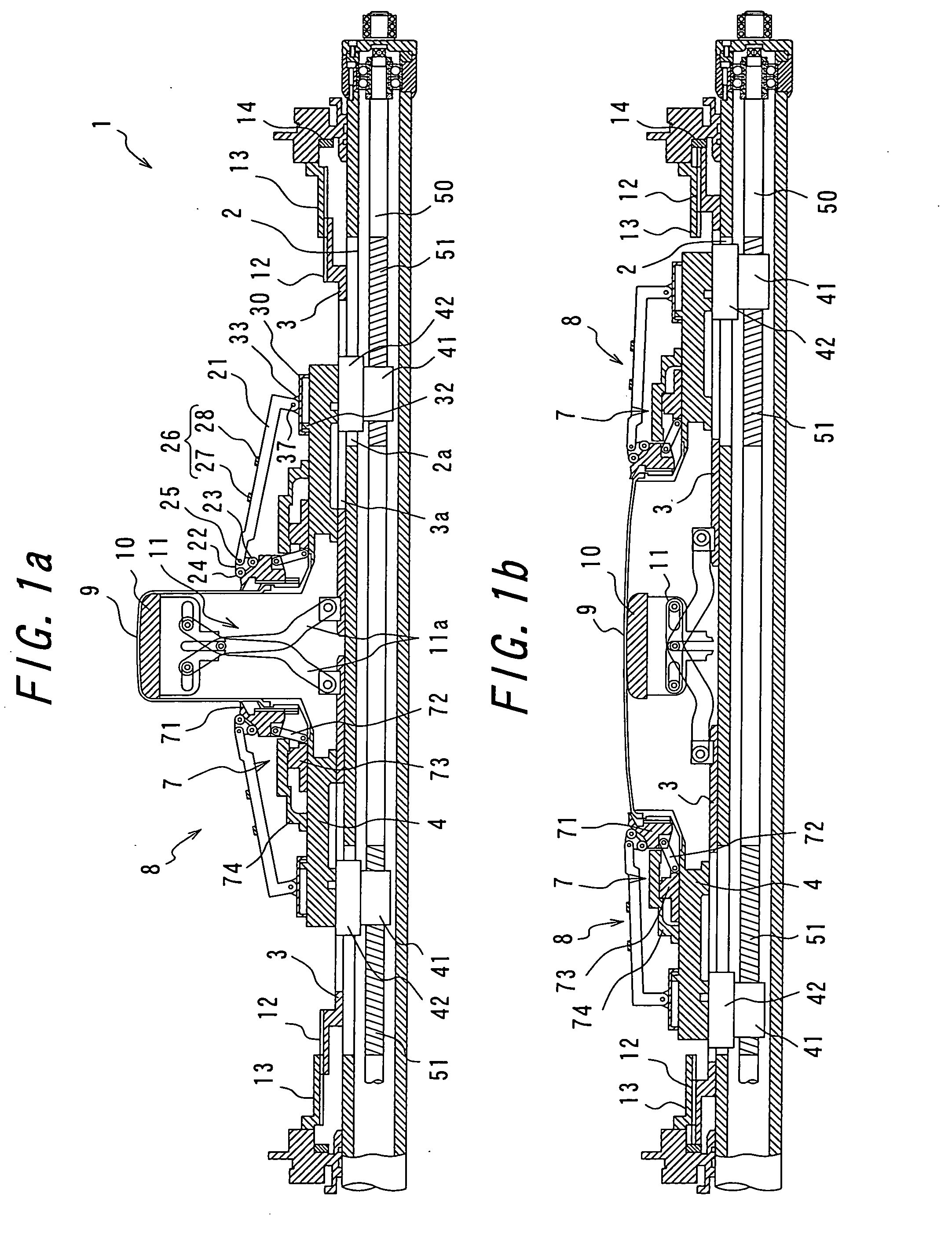
[0108] There will be explained embodiments of the present invention with reference to the accompanying drawings. FIG. 1 is a schematic cross-sectional view of substantially half of a tire building drum according to the present invention, including a center axis of the tire building drum.

[0109] This building drum 1 is provided with a pair of sleeves 3 to be displaced toward and away from each other in an axial direction on a center shaft 2. Provided at an outer peripheral surface of each sleeve 3 is an associated slider 4 to be displaced toward and away from each other on a center axis of the associated sleeve 3 and independently of the sleeve 3. Fixedly provided on an outer periphery of each slider 4 is associated bead lock means 7 for lockingly supporting an associated bead core, and each bead lock means 7 comprises: bead lock segments 71 which are circumferentially neighbored to each other to be expanded or contracted in an annular shape; associated links 72 having one ends hinged...

third embodiment

[0153] There will be explained a third embodiment according to the present invention based on FIGS. 13 through 21. FIG. 13 is a cross-sectional view of a tire building drum 100 of this embodiment.

[0154] This tire building drum 100 comprises: a hollow center shaft 110; a pair of bead lock means 120 for locking both bead cores; a pair of core bodies 130 for supporting a carcass band from a radial inside, and adapted to be axially displaced toward and away from each other and adapted to be deformed and thereby expanded or contracted; core-body expanding / contracting means 160 for expanding or contracting the core bodies 130; and a pair of folding-back means 170 for folding back carcass band side portions around associated bead cores, respectively; in which the drum is provided with a pair of sliders 140 to be displaced toward and away from each other on the center shaft 110, and each slider 140 has mounted thereon the bead lock means 120, core body 130 and folding-back means 170 positio...


PUM

PropertyMeasurementUnit
swinging forceaaaaaaaaaa
rotational speedaaaaaaaaaa
speedaaaaaaaaaa

Abstract

Tire building drum and tire building method, capable of assembling tire component members with high accuracy. A tire building drum is used, which includes at least one core body, which is disposed at an axial inside of a pair of bead lock means, and which comprises a plurality of sheets of rigid support members disposed in a toroidal shape and adapted to be displaced and thereby expanded or contracted. Bead cores are locked by the bead lock means, respectively, and a center portion of a carcass band is bulged while displacing the bead lock means close to each other. Back side portions of the carcass band are folded to radial outsides around the bead cores, respectively. The core body is then radially expanded to the maximum diameter while locking the bead cores, and tire component members are assembled onto the radially expanded core body.

Description

TECHNICAL FIELD [0001] The present invention relates to a tire building drum and a tire building method for conducting a tire building process from a carcass band up to formation of green tire on the same building drum, and particularly to those for molding a tire with high accuracy. BACKGROUND ART [0002] In molding a green tire, there has been conventionally conducted a method comprising the steps of: providing a cylindrical carcass band or green case on a shaping drum; bulging a center portion of the carcass band or green case into a toroidal shape; and uniting it to a belt / tread band established by bonding tire component members such as a belt member and a tread rubber separately on a belt / tread forming drum. [0003] However, in such a conventional method, the belt / tread band is once detached from the belt / tread forming drum, gripped from radially outside, moved to the shaping drum, and this gripping is released there so as to move the belt / tread band onto the shaping drum, with t...

Claims


Application Information

Patent Timeline
Patent Type & Authority Applications(United States)
IPC IPC(8): B29D30/32B29D30/24B29D30/36
CPCB29D30/245B29D30/32B29D30/36B29D2030/3257B29D2030/3264
Inventor IYANAGI, SATOSHIHIRAI, NOBUYUKIOGAWA, YUICHIRO
Owner BRIDGESTONE CORP
Why Eureka
Try Eureka