Winding tube
- Summary
- Abstract
- Description
- Claims
- Application Information
AI Technical Summary
Benefits of technology
Problems solved by technology
Method used
Image
Examples
Example
DETAILED DESCRIPTION OF THE DRAWINGS
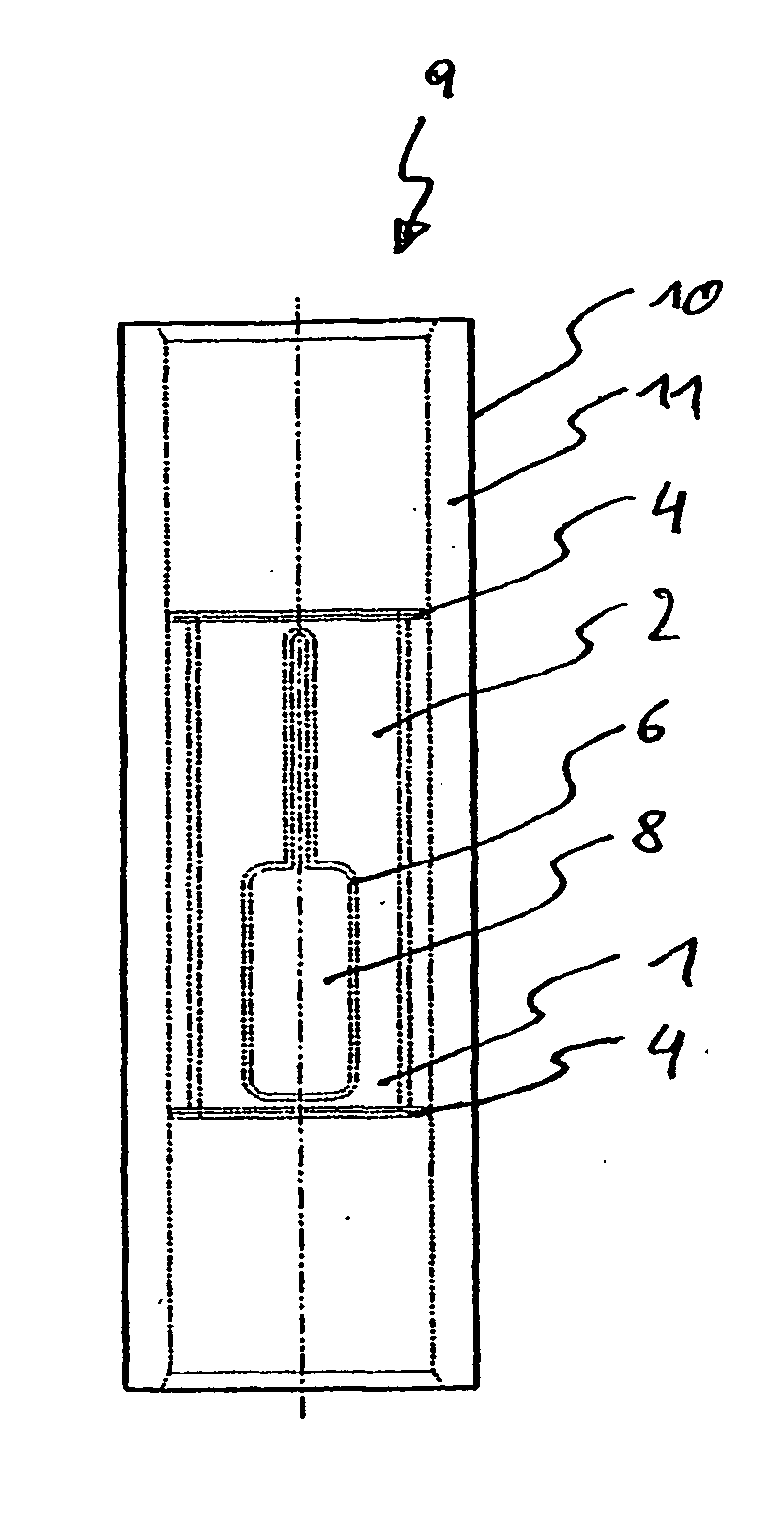
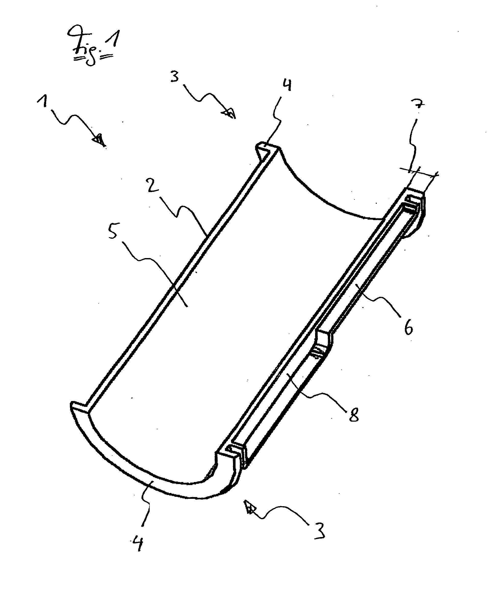
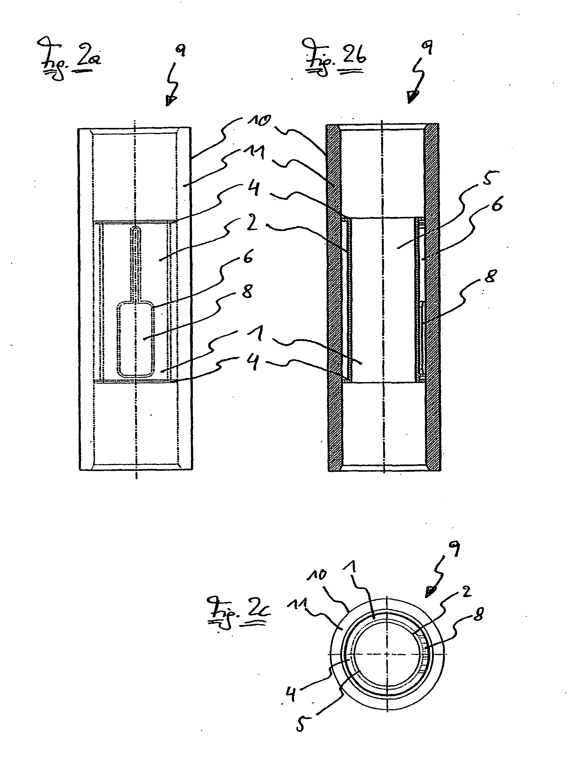
[0034]FIG. 1 shows tubular holding element 1 manufactured from plastic, preferably by an injection molding method. Holding element 1 consists of cylindrical, elongated insertion tube 2 comprising a radially projecting flange or collar 4 on both ends 3. Web 6 is attached to outer jacket surface 5 of holding element 1, has the same height 7 as collar 4 and completely surrounds scoop-shaped trough 8. Alternatively, collar 4 can also be provided with a plurality of radially running slots that increase elasticity and ensure a reliable fixing or clamping even considering deviations in the dimensions and shape of the inside diameter of the tube. It is also possible for winding tube 9 shown in FIGS. 2a to 2c to be provided with two adapters arranged on either or both ends, in addition to the central holding element. It is contemplated that the adapters can be removed from tube body 10 without being destroyed. The adapter may be provided on a tube body 10...
PUM
 Abstract
Description
Claims
Application Information
 - R&D
- Intellectual Property
- Life Sciences
- Materials
- Tech Scout
- Unparalleled Data Quality
- Higher Quality Content
- 60% Fewer Hallucinations
Browse by: Latest US Patents, China's latest patents, Technical Efficacy Thesaurus, Application Domain, Technology Topic, Popular Technical Reports.
© 2025 PatSnap. All rights reserved.Legal|Privacy policy|Modern Slavery Act Transparency Statement|Sitemap|About US| Contact US: help@patsnap.com


