Seating structure having flexible support surface

a flexible, seating technology, applied in the field of seating and seating, can solve the problems of excessive heat build-up between the seating surface and the occupant, difficulty in adjusting the firmness and corresponding support in different areas etc., and achieves the effect of increasing airflow, high strength, and reducing the amount of foam padded cushions

Inactive Publication Date: 2006-05-18
MILLERKNOLL INC
View PDF99 Cites 54 Cited by
  • Summary
  • Abstract
  • Description
  • Claims
  • Application Information

AI Technical Summary

Benefits of technology

[0011] In one aspect, the present invention relates to an improved method of constructing seating structures and surfaces, which provides greater comfort through superior surface adjustment for a variety of users. In one embodiment, the seating surface construction is comprised of a plurality of support sections (bosses / platforms) and of a plurality of web connectors interconnecting the support sections. In one embodiment, the support sections, or bosses / platforms, are more rigid than their corresponding web connectors. A variety of methods are disclosed for making the bosses / platforms with a greater degree of rigidity than the web connectors.
[0019] In various embodiments, the structure provides increased airflow to contact areas of the occupant's body, relative to foam for example. In addition, the seating surface can be made more efficiently and economically relative to foam and other types of seating surfaces. Moreover, the structure can be formed to provide different flexure characteristics in different areas of the seating structure.
[0020] The support member with its different materials also provides advantages. In particular, the plate-like structure can be provided in areas requiring high strength, with the remainder of the structure being made from a lighter and / or less expensive material.

Problems solved by technology

Problems can arise from each of these approaches.
For example, under normal manufacturing conditions, it can be difficult to vary the amount of firmness and corresponding support in different areas of a foam padded cushion.
Additionally, foam can lead to excessive heat-build-up between the seating surface and the occupant.
One of the problems with foam is the forming and molding process.
Current manufacturing technology makes it a relatively inefficient process compared with the manufacture of the other components that make up a chair or seating surface.
Another problem inherent to the use of foam is that in order to achieve a finished look, the cushions typically must be covered, e.g. upholstered.
When a manufacturer upholsters a cushion, a number of issues may arise.
Additionally, the amount of change in firmness can vary from fabric to fabric which results in an unpredictability of the firmness of a cushion from one manufactured unit to the next.
Such sizing can be difficult as a result of the differing mechanical properties found from one fabric to another.
Variations in the amount of stretch can lead to other problems.
Therefore, a proper size slipcover in one type of fabric, with its stretch characteristics, may be the wrong size in another type or style of fabric.
This approach also suffers from the aforementioned problems associated with using variable fabrics.
The other reality of cushion upholstery, regardless of the techniques used, is that whether it is done in a small shop or in a production situation, it can be the most labor-intensive aspect of chair / seating construction.
In the case of incorporating flex into the shells of a chair, it can be difficult to achieve the proper amount of flex in the right areas to give correct ergonomic comfort for a wide range of individuals.
In the case of a membrane approach, the curves imparted on the membrane by the frame are often simple in nature (non-compound) and thus cannot provide the proper contouring necessary for ergonomic comfort.
Also, this approach can lead to “hammocking,” where the areas adjacent a pressed area have the tendency of folding inward, squeezing the occupant, and not yielding the proper ergonomic curvatures.
An additional problem with membrane chairs is that the tension of the membrane may not be appropriate for all ranges of users.
Additionally, the purchaser ends up with a chair that at some point in the future may be the wrong size for a different user.
Metal, however, can be expensive to purchase as a raw material, as well as to form into a final product.
Moreover, the resultant chair is relatively heavy, leading to increased shipping costs and decreased portability.
These components, however, can be susceptible to wear and often cannot carry the necessary loads, for example in bearing.

Method used


Image

  • Seating structure having flexible support surface
  • Seating structure having flexible support surface
  • Seating structure having flexible support surface

Examples


Embodiment Construction

:

[0099] While the invention will be described in connection with one or more preferred embodiments, it will be understood that we do not intend to limit the invention to those embodiments. On the contrary, we intend to cover all alternatives, modifications and equivalents within the spirit and scope of the invention.

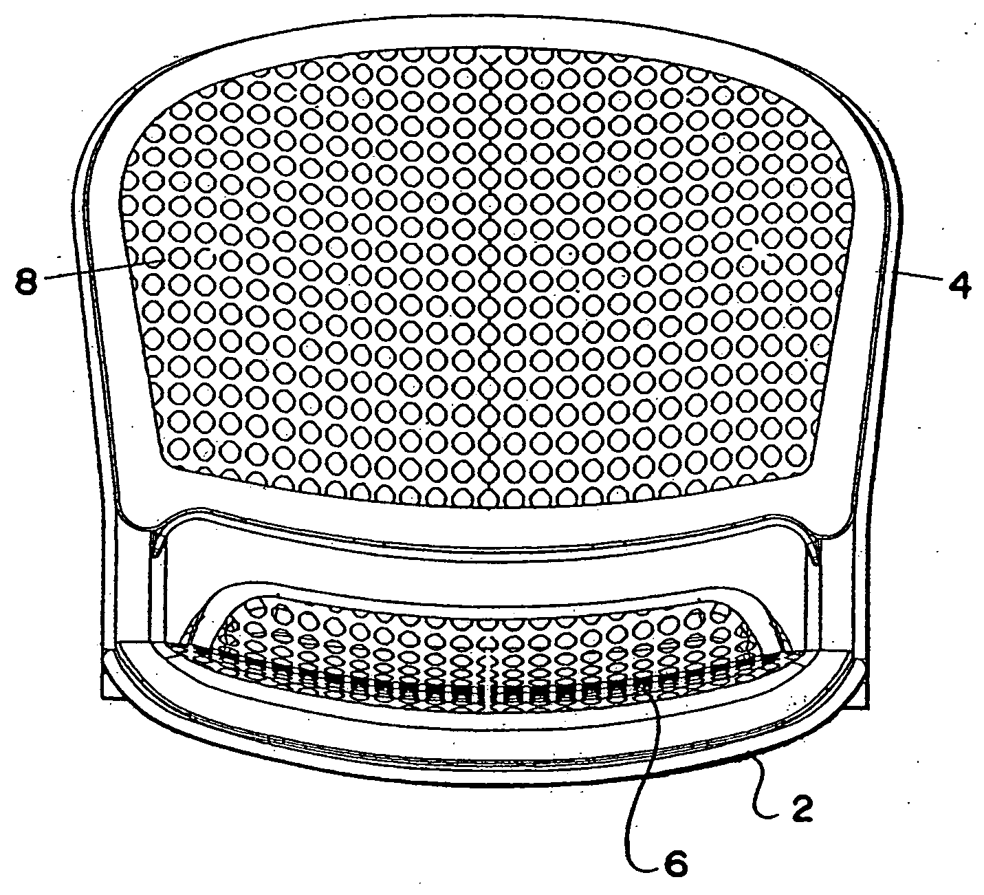
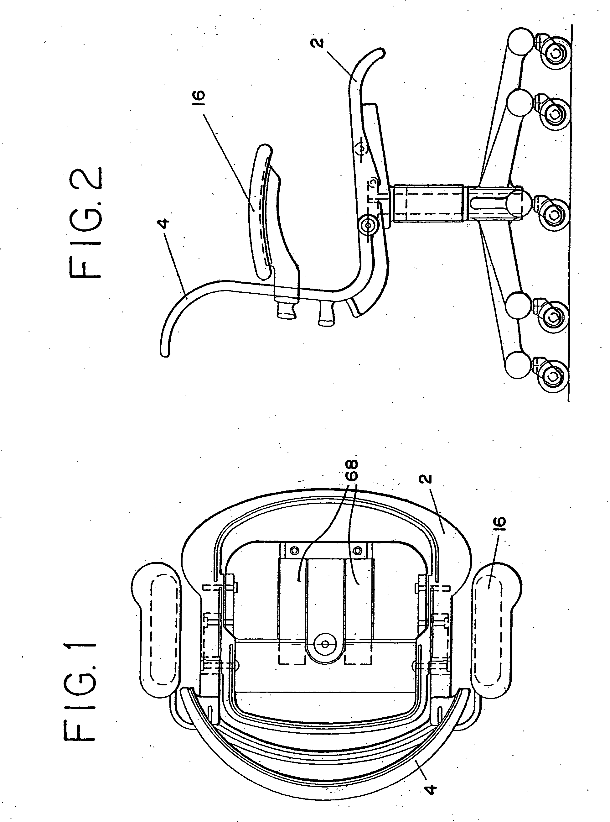
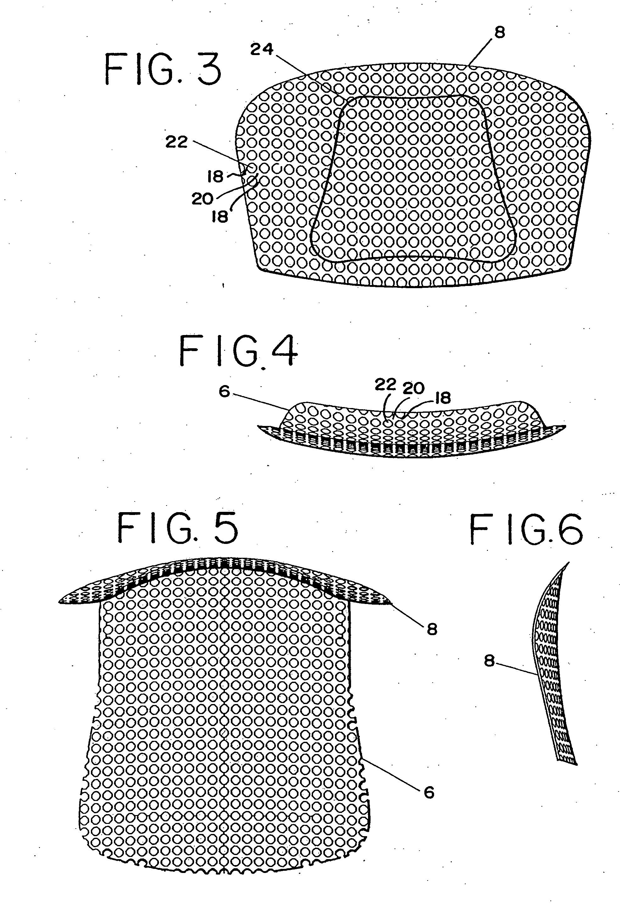
[0100] Referring to FIGS. 22-29, 38 and 39, various embodiments of a seating structure, configured as a chair, are shown. It should be understood that the term “seating structure” includes any structure intended to support the body of a user, whether standing, sitting or lying, and includes without limitation chairs, sofas, benches, automotive seats, stools, suspended structures, etc.

[0101] The chair 26 includes a back 28 having a pair of support arms 30 pivotally connected to a control housing 40 at a first pivot axis 32 and pivotally connected to opposite sides of a seat 44 at a second pivot axis 34. The seat 44 is pivotally connected to a link 42 at a third pivot ax...


PUM

PropertyMeasurementUnit
depthaaaaaaaaaa
depthaaaaaaaaaa
widthaaaaaaaaaa

Abstract

A seating structure includes a plurality of boss structures arranged in a pattern and a plurality of web structures joining adjacent boss structures within the pattern. At least some of the web structures are spaced apart such that they define openings therebetween. Adjacent rows of said web structures are spaced or staggered.

Description

[0001] This application is a continuation-in-part of U.S. patent application Ser. No. 10 / 809,279, filed Mar. 25, 2004, which is a continuation-in-part of U.S. patent application Ser. No. 09 / 897,153, filed Jun. 29, 2001, which claims the benefit of U.S. Provisional Application No. 60 / 215,257, filed Jul. 3, 2000, the entire disclosures of which are hereby incorporated herein by reference. This application also is a continuation-in-part of PCT Application PCT / US02 / 00024, filed Jan. 3, 2002, the entire disclosure of which is hereby incorporated herein by reference.FIELD OF INVENTION [0002] The present invention relates to chairs and seating normally associated with but not limited to residential or commercial office work. These chairs employ a number of structures and methods that enhance the user's comfort and promote ergonomically healthy sitting. These methods include various forms of padding and / or flexing of the seat and back as well as separate mechanical controls that control the...

Claims


Application Information

Patent Timeline
Patent Type & Authority Applications(United States)
IPC IPC(8): A47C7/02A47C5/12A47C7/16A47C7/28
CPCA47C1/03A47C1/03277A47C3/12A47C5/12A47C7/02A47C7/16A47C7/28A47C7/285A47C7/46
Inventor CARUSO, JEROME CARMELCARUSO, STEVEN JEROMEALDRICH, JOHN FREDRICHECTOR, ANDREW KEITHGRANZOW, THOMAS WILLIAMMILLER, DEAN THOMASPEEK, RICHARD THOMASEDINGER, BENJAMIN BOOTHAERTS, CHAD D.
Owner MILLERKNOLL INC
Why Eureka
Try Eureka