
Droplet ejection device

a technology of droplets and ejection devices, which is applied in printing and other directions, can solve the problems of increasing the cost required for the controller circuit and the increase of the cost of flexible flat cables, etc., and achieves the effect of reducing costs

Inactive Publication Date: 2006-05-18
BROTHER KOGYO KK
View PDF3 Cites 7 Cited by
  • Summary
  • Abstract
  • Description
  • Claims
  • Application Information

AI Technical Summary

Benefits of technology

[0010] It is therefore an object of the present invention to provide a droplet ejection device which is equipped with a controller circuit operable to control ejection of a droplet such as ink droplet through each of a large number of nozzles, and which has an arrangement permitting a reduction in the number of outputs provided in the controller circuit and accordingly enabling the controller circuit to be manufactured at a reduced cost. This object may be achieved according to any one of first through third aspects of the invention which are described below.
[0012] In the present droplet ejection device, each of the pressure chambers is arranged to correspond to at least two of the above-described at least four electrodes. The controller controls the ejection of the droplet from each of the pressure chambers, by controlling the electric voltage that is to be applied to each of the at least two electrodes to which the each of the pressure chambers corresponds. Since each of the electrodes is arranged to correspond to the pressure chamber or chambers belonging to the same group (which is formed by sorting in a corresponding one of the at least two different manners), the number of the required electrodes can be made smaller than the number of the pressure chambers (i.e., the number of the nozzles). It is therefore possible to reduce the number of outputs that are to be supplied from the controller, whereby the controller circuit can be produced in a reduced cost. Where the outputs are transmitted through output lines that are arranged in a flexible flat cable, the reduction of the number of the outputs eliminates or alleviates necessity of arranging the output lines in a high density.

Problems solved by technology

Such a large number of the required outputs leads to an increase in cost required for the controller circuit.
In the above-described conventional arrangement of the electrodes, if the number of columns is doubled to four, the required number of outputs of the individual electrodes is doubled to 300, whereby the costs required for the controller circuit and flexible flat cable are inevitably increased.

Method used


Image

  • Droplet ejection device
  • Droplet ejection device
  • Droplet ejection device

Examples


first embodiment

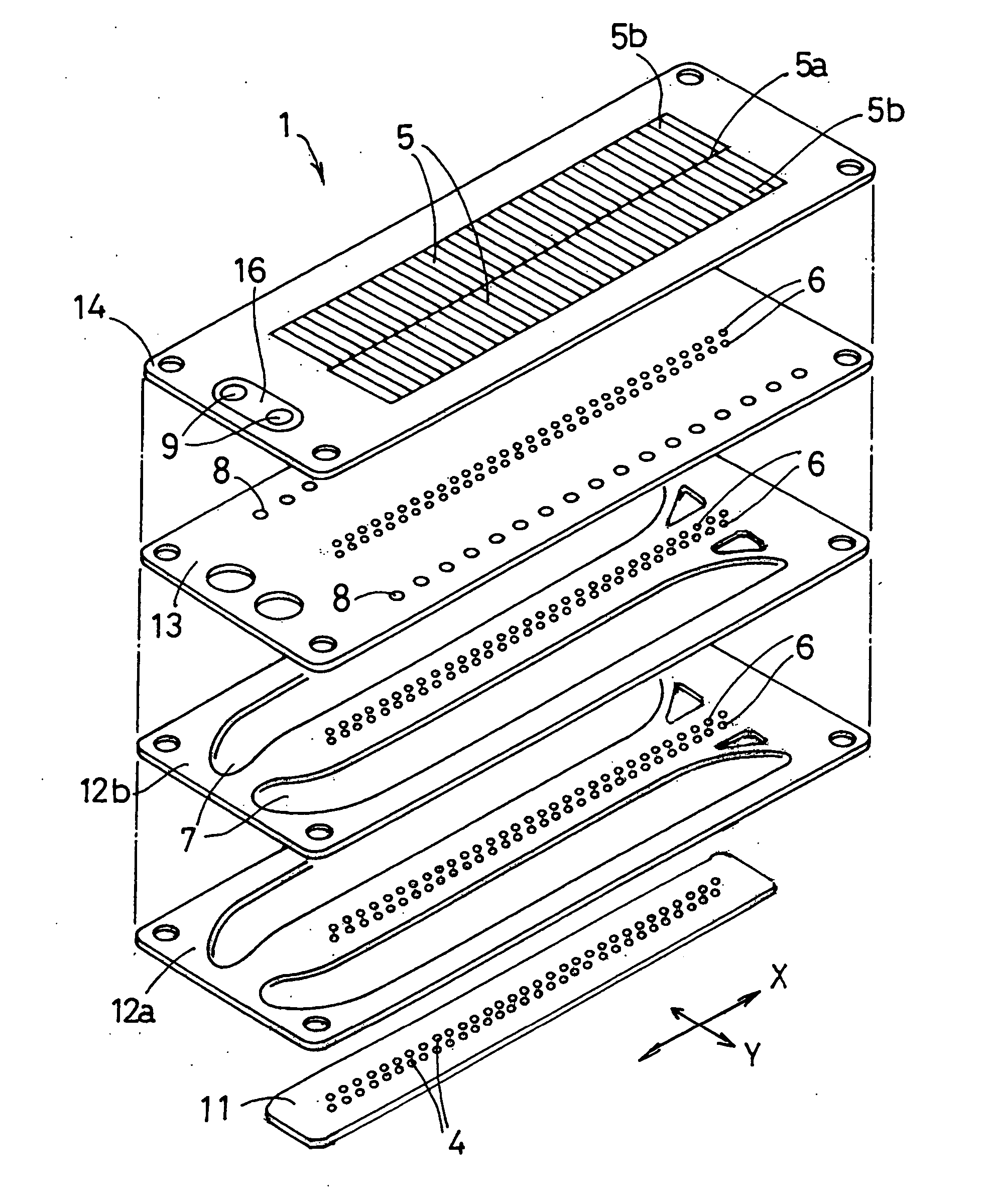
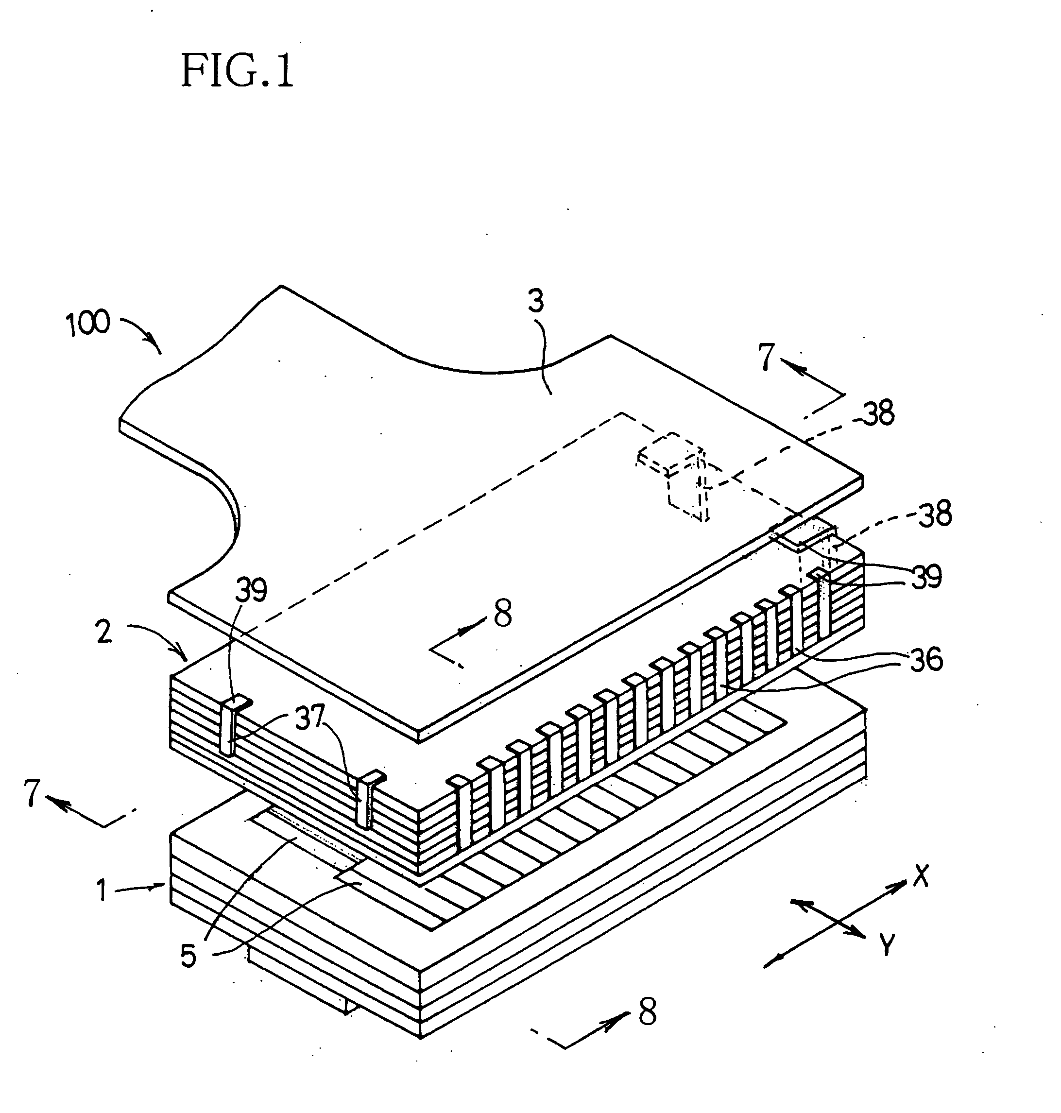
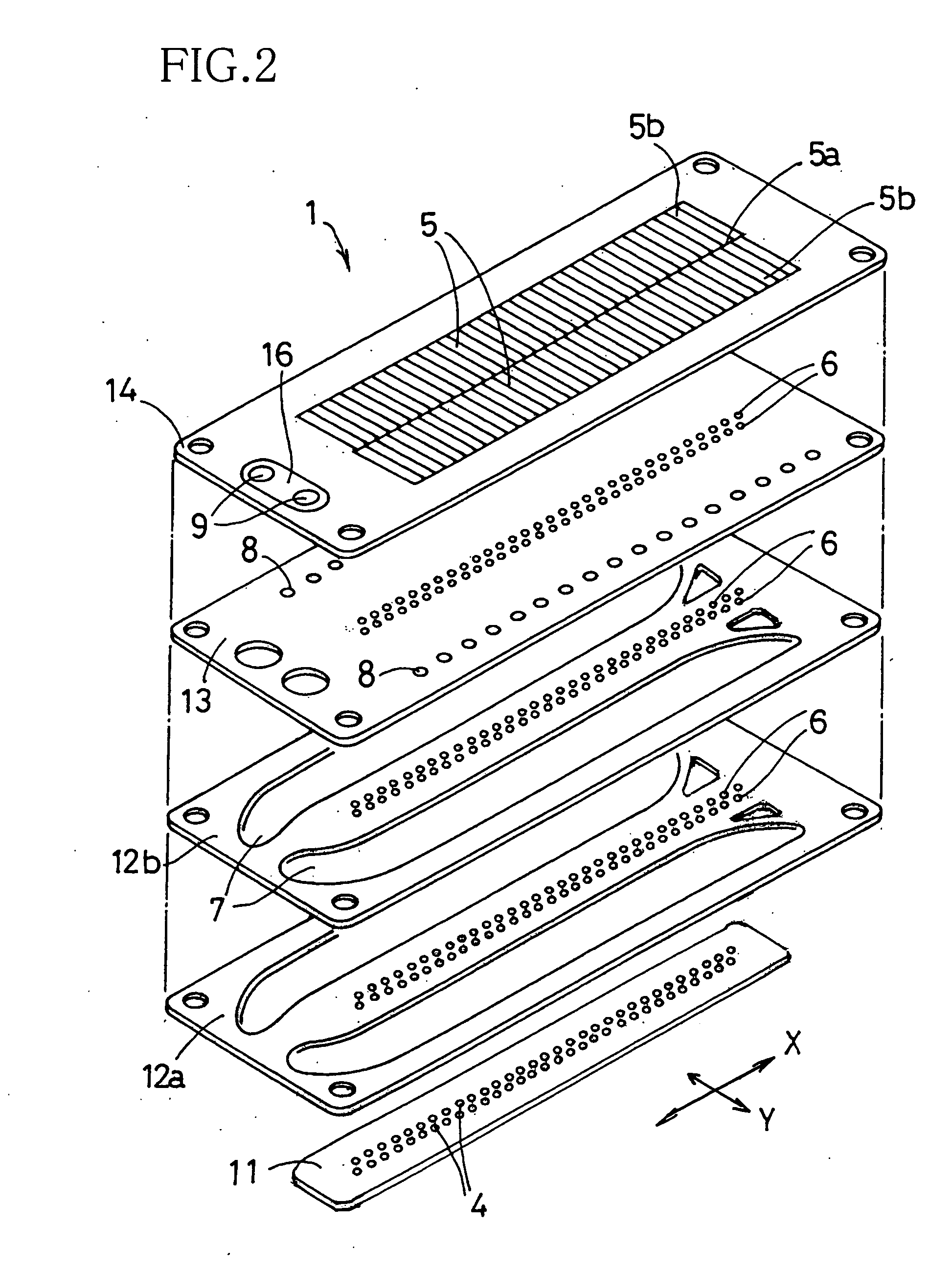
[0038] Referring to FIGS. 1-9, there will be described an inkjet head 100 constructed according to the invention. As shown in FIG. 1, the inkjet head 100 includes a cavity unit 1, a piezoelectric actuator unit 2 and a flexible flat cable 3. The cavity unit 1 has a plurality of nozzles 4 arranged on its front face (lower face as seen in FIG. 1), and a plurality of pressure chambers 5 held in communication with the respective nozzles 4. The actuator unit 2 is attached to a rear face (upper face as seen in FIG. 1) of the cavity unit 1, and has a plurality of actuators 20 corresponding to the respective pressure chambers 5. The flexible flat cable 3 is connected to a rear face of the actuator unit 2, for supplying drive voltages to the actuator unit 2. This inkjet head 100 is arranged such that an ink droplet is ejected downwardly through each of the nozzles 4 opening in the front face of the cavity unit 1 (see FIG. 8).

[0039] As shown in FIGS. 2 and 3, the cavity unit 1 includes a total...

second embodiment

[0081] There will be described a method of driving the inkjet head constructed with reference to FIG. 14. The rows and columns of the nozzles 4, pressure chambers 5 and actuators 20 are given the same denominations as in FIG. 10B. FIG. 14 shows, by way of example, operations of the actuators 20 of “ROW 1, COLUMN A”, “ROW 2, COLUMN A”, “ROW 1, COLUMN B” and “ROW 2, COLUMN B”, namely, a relationship between a combination of the drive voltages applied to the electrodes of each actuator 20 and an amount of displacements or deformations of the deformable portions of each actuator 20, in a case where the ink droplet is to be ejected from only the pressure chamber 5 (nozzle 4) of “ROW 1, COLUMN A” while the ink droplet is not to be ejected from the other pressure chambers 5 (nozzles 4) of “ROW 2, COLUMN A”, “ROW 1, COLUMN B” and “ROW 2, COLUMN B”. The ink droplet is ejected from the corresponding pressure chamber 5, where a sum of amounts of deformations of the deformable portions exceeds...


PUM


Abstract

A droplet ejection device including: a cavity unit having nozzles and pressure chambers; an actuator unit including actuators corresponding to the respective pressure chambers, such that each actuator is operable to change a volume of the corresponding pressure chamber whereby a droplet is ejected from the corresponding pressure chamber through the corresponding nozzle; and a controller for controlling ejection of the droplet from each pressure chamber. The actuators are provided by at least four electrodes and a piezoelectric body. The pressure chambers are sorted into groups in at least two different manners, such that each pressure chamber belongs to at least two groups formed by sorting in the respective different manners. Each of the electrodes is arranged to correspond to at least one of the pressure chambers belonging to one of the groups formed by sorting in a corresponding one of the at least two different manners, so that each pressure chamber corresponds to at least two of the electrodes. The controller controls an electric voltage to be applied to each of the electrodes, for controlling ejection of the droplet from each of the pressure chambers.

Description

[0001] This application is based on Japanese Patent Application No. 2004-333345 filed in Nov. 17, 2004, the content of which is incorporated hereinto by reference. BACKGROUND OF THE INVENTION [0002] 1. Field of the Invention [0003] The present invention relates to a droplet ejection device such as an inkjet head. [0004] 2. Discussion of Related Art [0005] As a droplet ejection device, there is known an inkjet head operable to eject an ink droplet. U.S. Pat. No. 6,648,455 (corresponding to JP-2002-59547A) discloses an inkjet head including: (a) a cavity unit having a plurality of nozzles and a plurality of pressure chambers held in communication with the respective nozzles; (b) a piezoelectric actuator unit including a plurality of actuators operable to change a volume of a corresponding one of the pressure chambers; and (c) a flexible flat cable for supplying a drive voltage to each of the actuators. [0006] In the inkjet head disclosed in U.S. Pat. No. 6,648,455, the plurality of pr...

Claims


Application Information

Patent Timeline
Patent Type & Authority Applications(United States)
IPC IPC(8): B41J2/045
CPCB41J2/04543B41J2/04581B41J2/14209B41J2002/14217B41J2002/14225B41J2002/14306B41J2002/14491
Inventor TAKAHASHI, YOSHIKAZU
Owner BROTHER KOGYO KK
Learn More