Video image encoding method, video image encoder, and video image encoding program

a video image and encoder technology, applied in the field of video image encoders video image encoders, etc., can solve the problems of increasing the cost of encoders, and achieves less image quality degradation, good encoding efficiency, and increased computation or hardware scale

Inactive Publication Date: 2006-05-18
KK TOSHIBA
View PDF0 Cites 88 Cited by
  • Summary
  • Abstract
  • Description
  • Claims
  • Application Information

AI Technical Summary

Benefits of technology

[0010] The present invention is directed to a video image encoding method, a video image encoder, and a video image encoding program product which allows to select a predicti...

Problems solved by technology

In the method of executing actual encoding and finding the code amount and the encoding distortion for each prediction mode, however, if the number of prediction modes is large, the computation amount and the hardware scale required for encoding grow, resulting in an increase in the cost of the encoder although it is made possible to appropriately select the prediction mode for providing good encoding efficiency and less ima...

Method used


Image

  • Video image encoding method, video image encoder, and video image encoding program
  • Video image encoding method, video image encoder, and video image encoding program
  • Video image encoding method, video image encoder, and video image encoding program

Examples


first embodiment

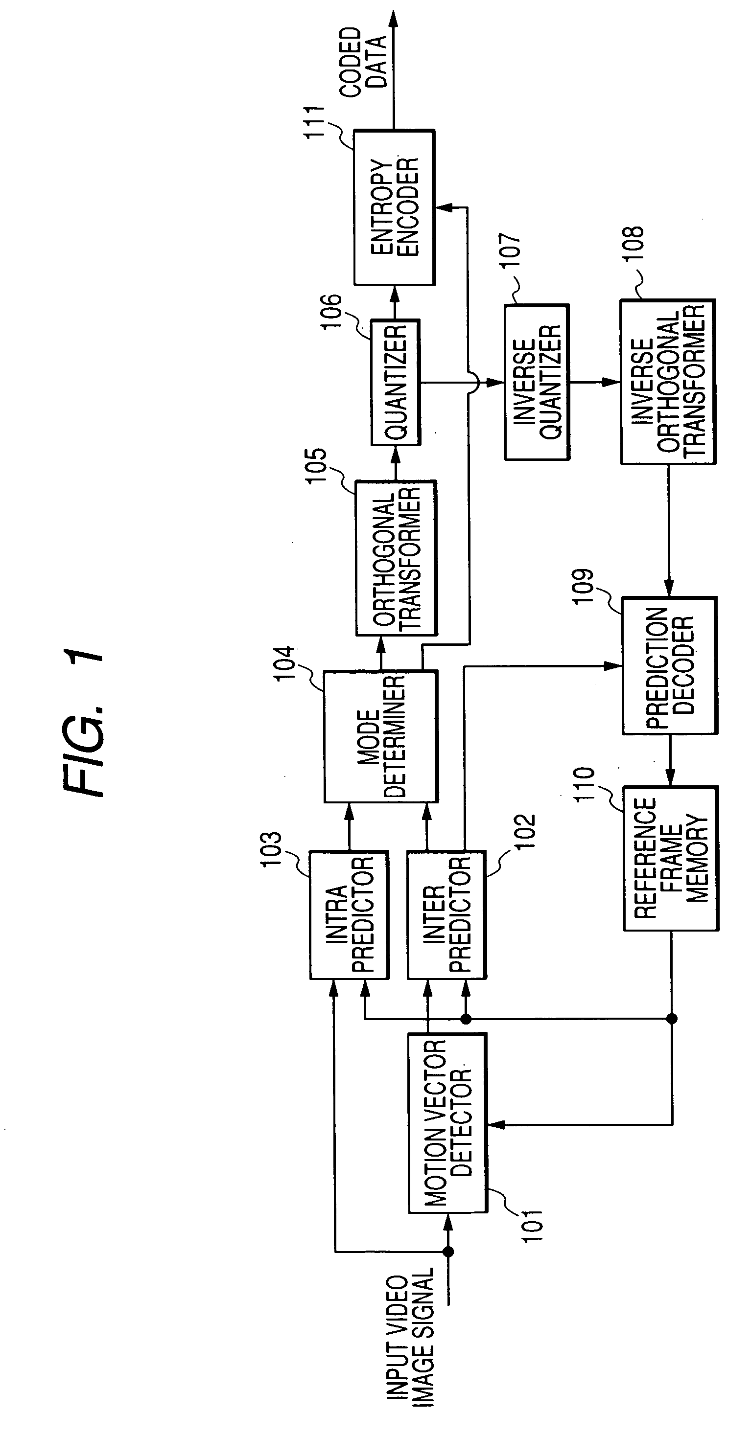
[0037]FIG. 1 is a block diagram to show a configuration of a video image encoder according to a first embodiment.

[0038] The video image encoder according to the first embodiment includes a motion vector detector 101, an inter predictor (interframe predictor) 102, an intra predictor (intraframe predictor) 103, a mode determiner 104, an orthogonal transformer 105, a quantizer 106, an inverse quantizer 107, an inverse orthogonal transformer 108, a prediction decoder 109, reference frame memory 110, and an entropy encoder 111.

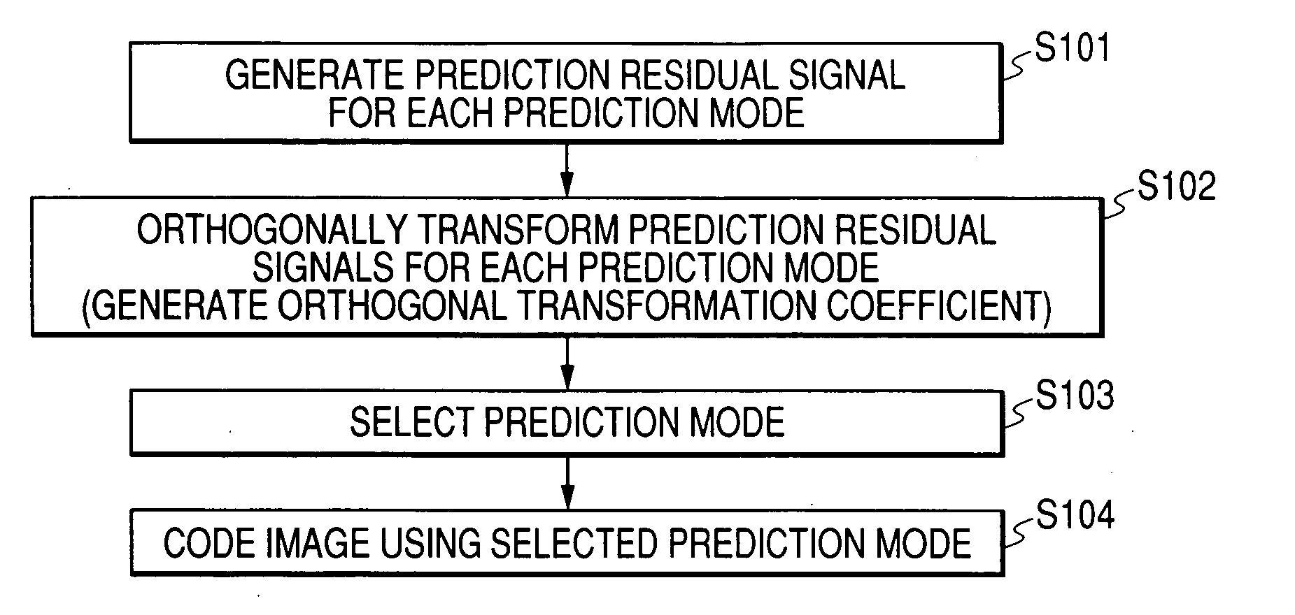
[0039] The operation of the video image encoder according to the first embodiment will be described with FIGS. 1 and 2. FIG. 2 is a flowchart to show the operation of the video image encoder according to the first embodiment.

[0040] When an input image signal is input to the video image encoder, the input image signal is divided into pixel blocks each of a given size and a prediction image signal is generated according to a plurality of prediction modes for each ...

second embodiment

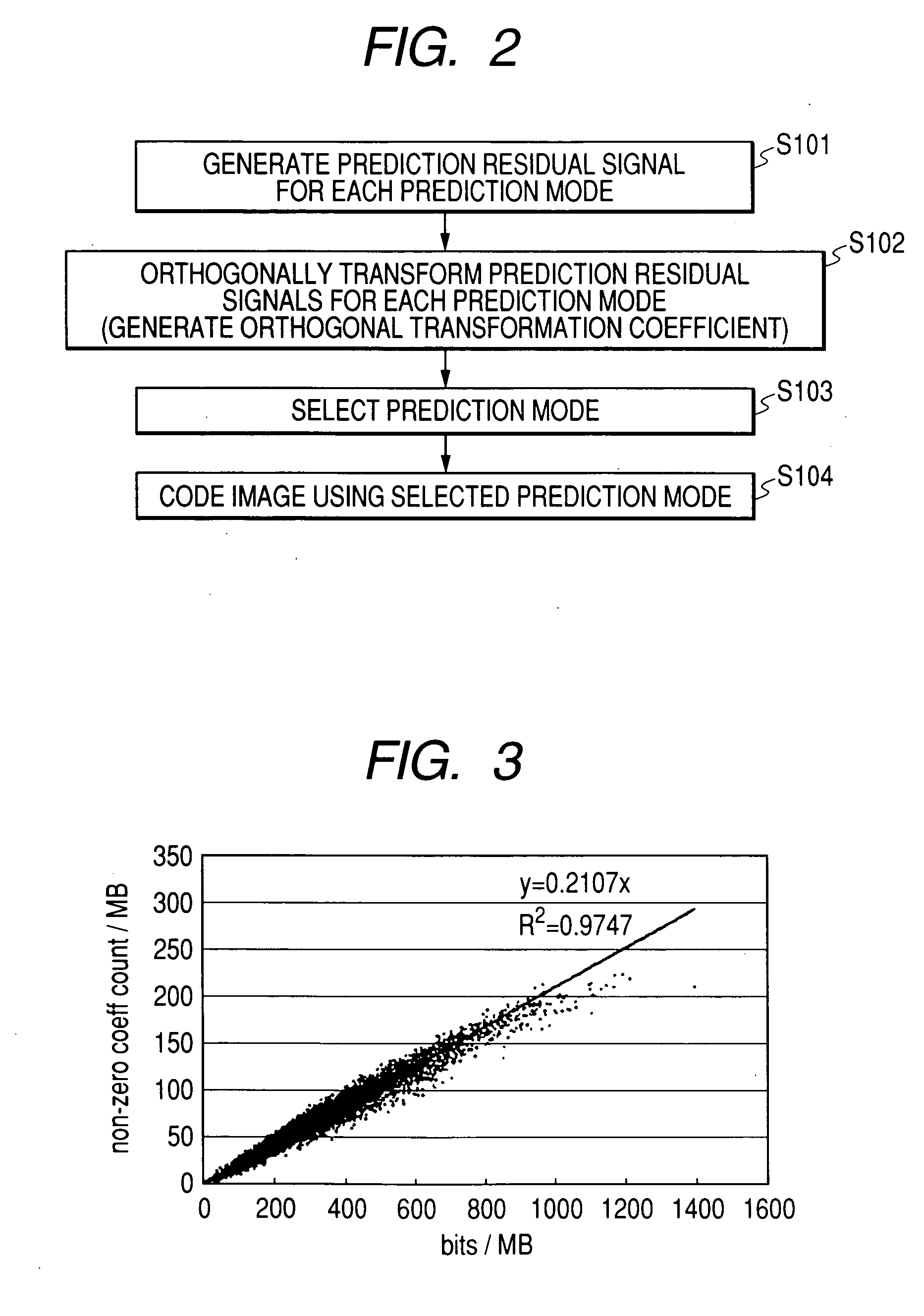
[0063] In the first embodiment, using the fact that there is a correlation between the code amount produced by encoding the orthogonal transformation coefficient of the prediction residual signals and the number of coefficients becoming non-zero as quantization processing is performed, of the orthogonal transformation coefficients of the prediction residual signals, the number of non-zero coefficients is found for each prediction mode and the prediction mode corresponding to the smallest number of non-zero coefficients is selected.

[0064] In a second embodiment, a prediction mode selection method will be described also considering the correlation difference for each prediction mode.

[0065]FIG. 5 is a block diagram to show the configuration of a video image encoder according to the second embodiment.

[0066] The video image encoder according to the second embodiment includes a motion vector detector 201, an inter predictor 202, an intra predictor 203, a mode determiner 204, an orthogo...

third embodiment

[0081] In the second embodiment, the code amount produced by encoding each pixel block is estimated from the number of coefficients becoming non-zero as quantization processing is performed, of the orthogonal transformation coefficients of the prediction residual signals, and the prediction mode wherein the estimated code amount becomes the minimum is selected.

[0082] In a third embodiment, a method of selecting a prediction mode by also estimating the code amount produced by encoding additional information relevant to the prediction mode such as a motion vector to generate a prediction image and the number of a reference image to generate a prediction image will be described.

[0083]FIG. 7 is a block diagram to show the configuration of a video image encoder according to the third embodiment.

[0084] The video image encoder according to the third embodiment includes a motion vector detector 301, an inter predictor 302, an intra predictor 303, a mode determiner 304, an orthogonal tran...


PUM


Abstract

A method for encoding a video image includes: generating a prediction image for each of a plurality of pixel blocks that are divided from an input image into a predetermined size, and generating a prediction residual signal that indicates prediction residual between the prediction image and each of the pixel blocks, for each of a plurality of prediction modes; obtaining an orthogonal transformation coefficient by performing orthogonal transformation to the prediction residual signal corresponding to each of the prediction modes; selecting a target prediction mode from among the prediction modes based on a number of the orthogonal transformation coefficients that become non-zero as a quantization processing is performed; encoding each of the pixel blocks in the target prediction mode respectively selected.

Description

RELATED APPLICATIONS [0001] The present disclosure relates to the subject matter contained in Japanese Patent Application No. 2004-328456 filed on Nov. 12, 2004, which is incorporated herein by reference in its entirety.BACKGROUND [0002] 1. Field of the Invention [0003] The present invention relates to a video image encoding method, a video image encoder, and a video image encoding program product for causing a computer system to select a prediction mode for providing good encoding efficiency and less image quality degradation from among prediction modes and to encode a video image. [0004] 2. Description of the Related Art [0005] In the international standards of video image encoding methods such as MPEG-2, MPEG-4, and H.264, a plurality of modes (prediction modes) exist in selecting methods of a reference image to generate a prediction image and a prediction block shape, and generation methods of a prediction residual signal, and the image to be encoded is encoded according to one ...

Claims


Application Information

Patent Timeline
IPC IPC(8): G06K9/36H04N19/50H04N19/103H04N19/109H04N19/11H04N19/136H04N19/137H04N19/147H04N19/154H04N19/176H04N19/196H04N19/40H04N19/42H04N19/503H04N19/51H04N19/567H04N19/593H04N19/60H04N19/91
CPCH04N19/176H04N19/147H04N19/18H04N19/107H04N19/146H04N19/61
Inventor KOTO, SHINICHIROASANO, WATARU
Owner KK TOSHIBA
Why Eureka
Try Eureka