Image processing apparatus

a technology of image processing and apparatus, applied in the field of image processing apparatus, can solve the problems of increasing power consumption, difficult to generate lossless images, and inability to allow information truncation, so as to reduce image noise, less degradation of image quality, and less noise.

Inactive Publication Date: 2010-03-25
RENESAS ELECTRONICS CORP
View PDF6 Cites 17 Cited by
  • Summary
  • Abstract
  • Description
  • Claims
  • Application Information

AI Technical Summary

Benefits of technology

[0014]By selecting a compression rate depending on a quantity of image data loss, it is possible to reproduce an image with less noise, i.e., less degradation of image quality. Especially, when a large quantity of data loss is determined, original image data is used instead of an interpolated frame, so that a noisy interpolated frame is not generated. Noise (errors) can be concealed and overall image quality can be improved.

Problems solved by technology

However, in the case of lossless image compression processing, truncation of information is not allowed.
This poses a problem of increasing power consumption.
So, it is hard to generate a lossless image.
However, even in this Patent Document 1, a lossy image involving some noise is reproduced and it is hard to reproduce a lossless image.
Particularly when frame interpolation processing is performed for frame rate conversion, if a decompressed image is lossy, the resulting interpolated frame would have large noise and degradation of image quality is unavoidable.

Method used


Image

  • Image processing apparatus
  • Image processing apparatus
  • Image processing apparatus

Examples


embodiment 1

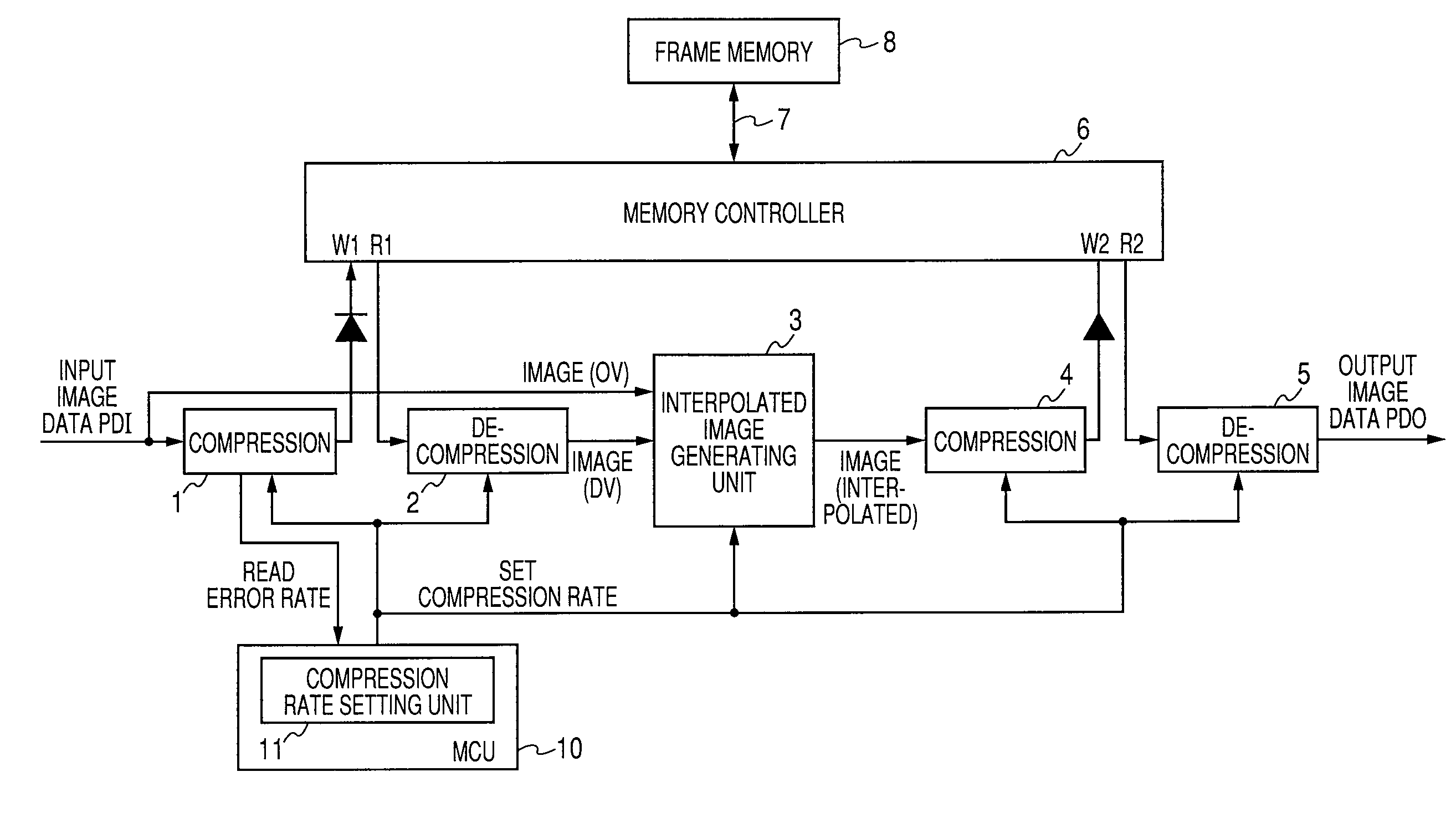
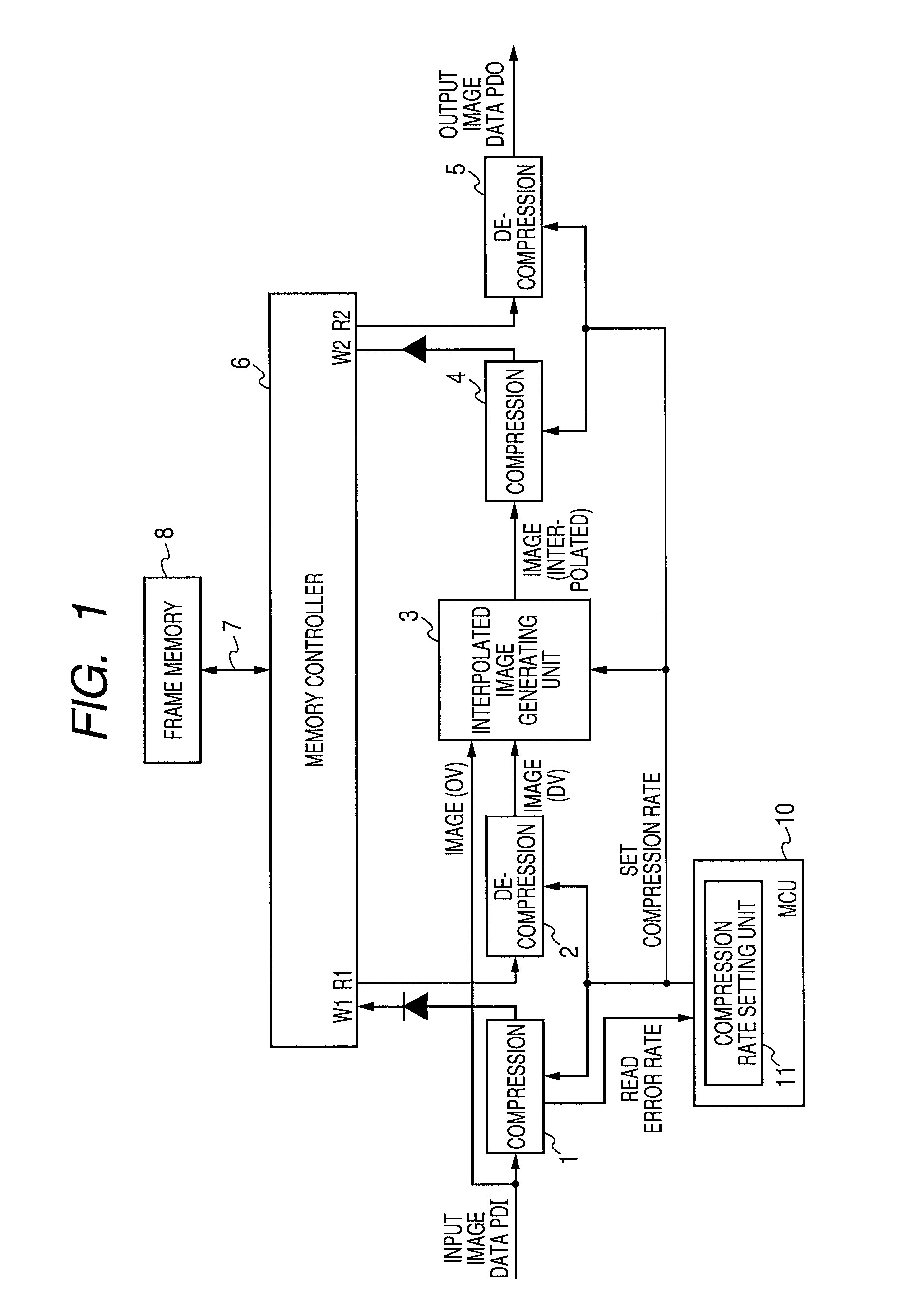
[0023]FIG. 1 is a diagram that schematically shows a configuration of an image processing apparatus according to Embodiment 1 of the invention. In FIG. 1, the image processing apparatus includes a compression unit 1 and a decompression unit 2 for compressing and decompressing input image data, an interpolated image generating unit 3 for generating an interpolated image, and a compression unit 4 and a decompression unit 5 for compressing and decompressing the interpolated image, respectively.

[0024]The compression unit 1 has a function to determine, for example, an error rate in the data amount of input image data PDI, and adaptively compresses the input image data PDI depending on the error rate (the quantity of data loss). The rate at which the compression unit 1 compresses input image data (compression rate) is variable and its compression algorithm is changed (i.e., the compression rate is changed) depending on image features of input image data PDI, such as its data amount. The d...

embodiment 2

[0070]FIG. 8 is a diagram that schematically shows an overall configuration of an image processing apparatus according to Embodiment 2 of the invention. In FIG. 8, the image processing apparatus generates image data to be delivered to a liquid crystal panel 46. this image processing apparatus includes a video processor 40, a frame rate conversion unit 42 which coverts the frame rate of image data from the video processor 40, and a timing controller 44 which generates image data for driving the liquid crystal panel 46 from the image data from the frame rate conversion unit 42.

[0071]Frame memories 46 and 48 are provided, respectively, for the video processor 40 and for the timing controller 44. These frame memories 46 and 48 are used for temporary storage of image data by the video processor 40 and the timing controller 44, respectively.

[0072]Using the frame memory 46 as a working area, the video processor 40 performs I / P conversion processing to convert interlaced frames of image dat...


PUM


Abstract

The invention is intended to reduce overall image degradation when frame interpolation is performed by means of an adaptive image compression technique. A compression unit which adaptively compresses input image data, determines an error rate, i.e., a quantity of data loss, depending on input image data. A compression rate is set, depending on the determined error rate (or the quantity of data loss). For an image that is likely to be degraded by compression because of a large error rate determined for it, a process of generating an interpolated image by an interpolated image generating unit is disabled and an original image is used instead of an interpolated frame.

Description

CROSS-REFERENCE TO RELATED APPLICATIONS[0001]The disclosure of Japanese Patent Application No. 2008-245670 filed on Sep. 25, 2008 including the specification, drawings and abstract is incorporated herein by reference in its entirety.BACKGROUND OF THE INVENTION[0002]The present invention relates to an image processing apparatus and, particularly, to a configuration of an image processing apparatus which generates an interpolated image by means of image compression processing in which an image is compressed for data amount reduction.[0003]In image processing applications, it is required to process large amounts of data such as voice and video. To reduce data amounts when performing transfer of and storing of such image data into memory, image compression processing is performed. For image compression processing, a frame memory is generally used as a working area and image data of one or more frames are stored into this frame memory.[0004]Meanwhile, along with recent trends toward visu...

Claims


Application Information

Patent Timeline
Patent Type & Authority Applications(United States)
IPC IPC(8): H04N7/12G09G3/20G09G3/36H04N19/89G09G5/00H04N7/01H04N19/00H04N19/12H04N19/146H04N19/172H04N19/189H04N19/423H04N19/426H04N19/587
CPCG09G5/36G09G2320/0693G09G2340/02H04N7/0127H04N7/0135H04N19/587H04N19/12H04N19/132H04N19/14H04N19/428H04N19/172
Inventor TERASHIMA, KAZUAKI
Owner RENESAS ELECTRONICS CORP
Why Eureka
Try Eureka