
Developer supply container and image forming apparatus

Inactive Publication Date: 2006-05-18
CANON KK
View PDF15 Cites 64 Cited by
  • Summary
  • Abstract
  • Description
  • Claims
  • Application Information

AI Technical Summary

Benefits of technology

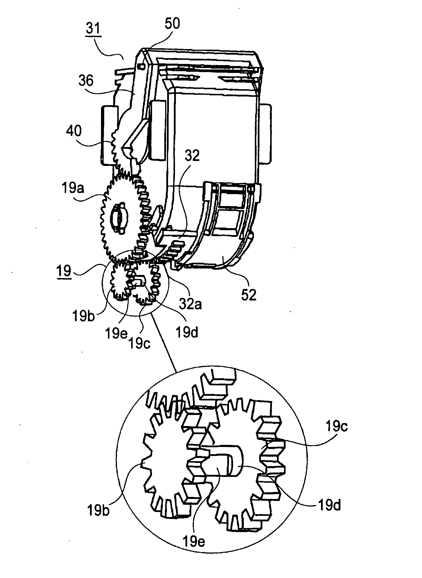
[0017] An object of the present invention is to provide a developer supply container, detachably mountable to an main assembly of an image forming apparatus, capable of preventing a first driving force transmitting portion for opening and closing a developer discharge opening and a second driving force transmitting portion, which are connected via a driving force relay portion provided to the image forming apparatus main assembly, from deviating from a predetermined position to be engaged with a gear of the main assembly.

Problems solved by technology

The toner as the developer is very fine powder, so that there has arisen such a problem that the toner scatters from a minute spacing between constitutional parts due to operational vibrations or the like during a toner supply operation, thus contaminating a user or surrounding parts with the toner.
In such a method, it is difficult to discharge the toner naturally by the action of gravity or the like, so that the image forming apparatus is generally provided with any toner stirring conveyance means.
In such a restricted condition of the rotational movement range, when the above described phase difference is caused to occur, there are possibilities that the apparatus shutter is not sufficiently closed by the restricted rotational movement and that the apparatus shutter runs against an opposite closing position before the handle is rotationally moved in a predetermined amount of rotation, so that the handle cannot be rotationally moved to prevent the toner cartridge from being removed from the main assembly of the image forming apparatus.

Method used


Image

  • Developer supply container and image forming apparatus
  • Developer supply container and image forming apparatus
  • Developer supply container and image forming apparatus

Examples


Embodiment Construction

[0059] Embodiments of a developer supply container and an image forming apparatus according to the present invention will be described with reference to the drawings.

(General Structure)

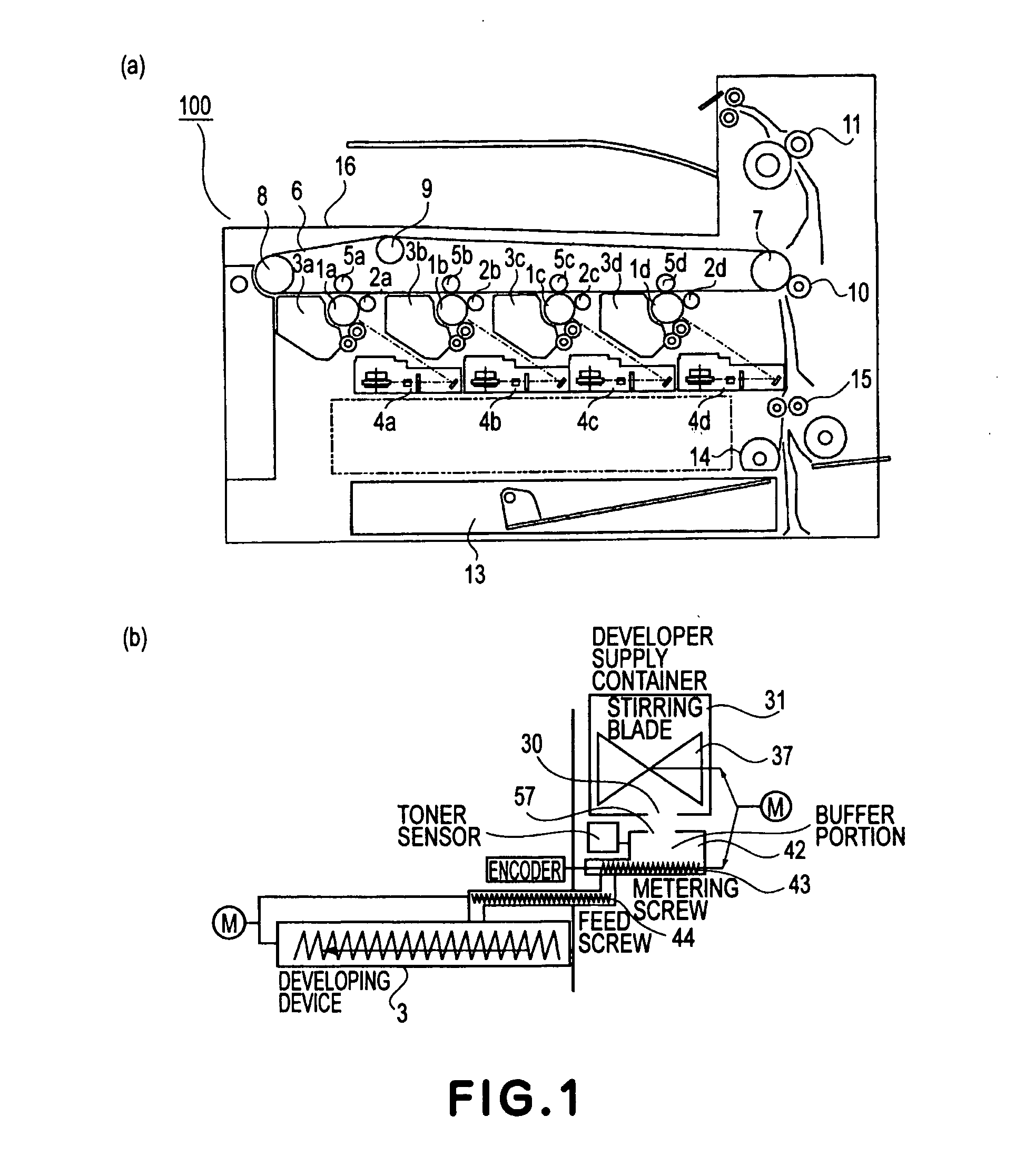
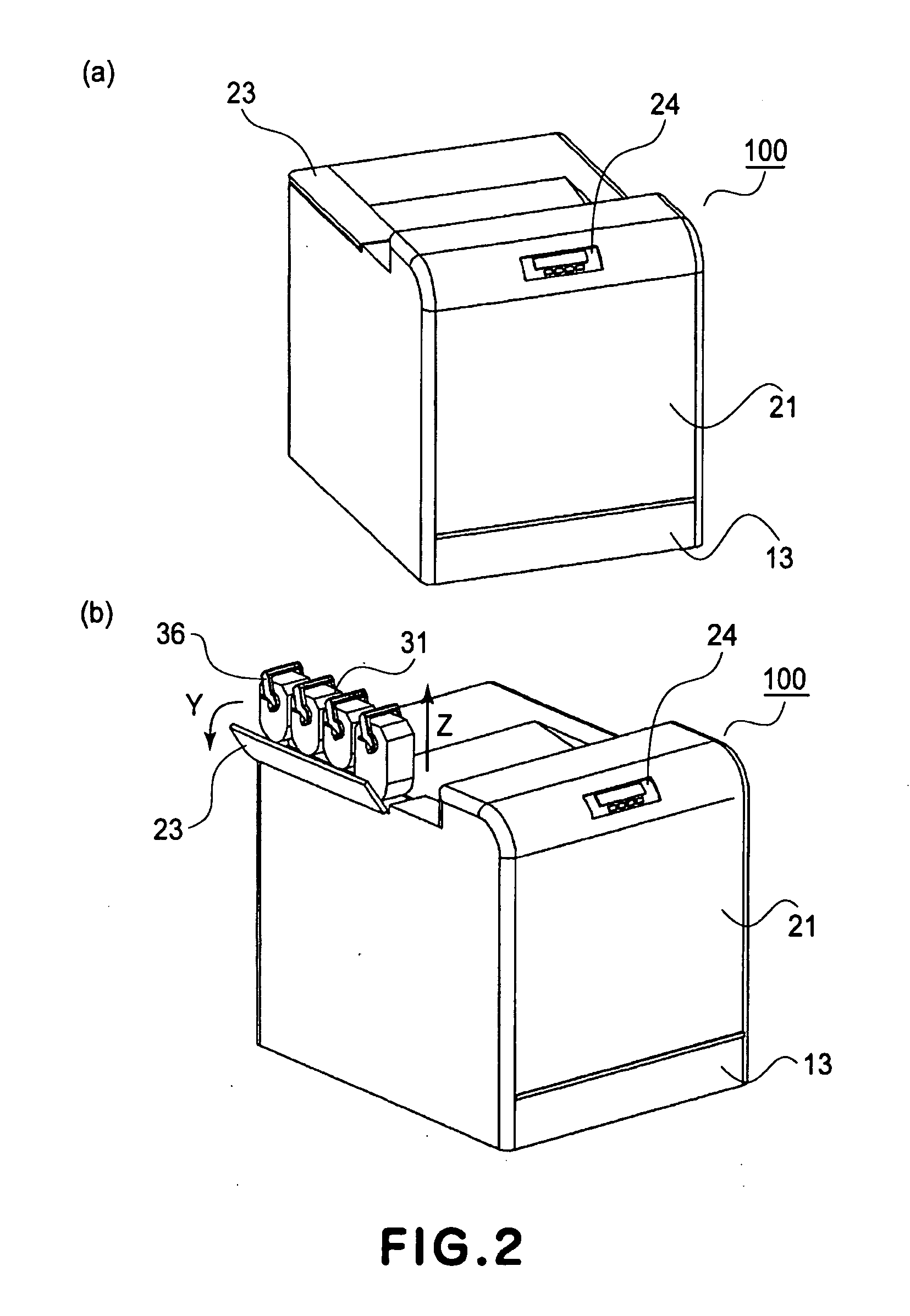
[0060] A main assembly 100 of an image forming apparatus according to this embodiment and a developer supply container to be mounted into the image forming apparatus main assembly 100 will be described with reference to the drawings. First, a general structure of the image forming apparatus main assembly 100 will be described with reference to FIGS. 1 and 2. FIG. 1(a) is a schematic sectional view of the image forming apparatus main assembly 100 of this embodiment as seen in a left side surface of the image forming apparatus; FIG. 1(b) is a conceptual view showing a conveyance process of developer from the developer supply container to the image forming apparatus main assembly 100; FIG. 2(a) is an external perspective view of the image forming apparatus main assembly 100; and FIG. 2(b) is an extern...


PUM


Abstract

A developer supply container detachably mountable to a main assembly of an image forming apparatus includes a developer discharge opening to be disposed opposite to a developer receiving opening of the apparatus main assembly; an operation member capable of performing a moving operation in a mounted state of the container; an open / close driving force transmitting portion provided to the operation member; a driving force transmitting portion for transmitting a driving force, to a apparatus shutter member, from the open / close driving force transmitting portion through an open / close driving force relay gear train provided to the apparatus main assembly; and a container-side abutting portion for abutting against a gear-side abutting portion provided to at least one gear of the relay gear train. When the developer supply container is mounted into the apparatus main assembly, the container-side abutting portion abuts against the gear-side abutting portion to rotate the relay gear train toward an initial position.

Description

FIELD OF THE INVENTION AND RELATED ART [0001] The present invention relates to a developer supply container for supplying a powdery developer to an electrophotographic image forming apparatus for forming an image with the developer, and the image forming apparatus using the developer supply container. [0002] Here, the electrophotographic image forming apparatus is an image forming apparatus for forming an image on a recording medium in accordance with an electrophotographic image forming method. Examples of the electrophotographic image forming apparatus may include an electrophotographic copying machine, electrophotographic printers (such as a laser beam printer and an LED printer), a facsimile apparatus, a word processor, etc. [0003] In the image forming apparatus such as the electrophotographic copying machine, the laser beam printer, etc., a latent image is formed by selectively exposing an electrically uniformly charged surface of a photosensitive drum to light and is developed...

Claims


Application Information

Patent Timeline
IPC IPC(8): G03G15/08
CPCG03G2215/067G03G2215/0692G03G15/0868G03G15/0886G03G15/0875G03G15/06
Inventor SASAE, KAZUYOSHINAKAJIMA, NOBUOTAZAWA, FUMIO
Owner CANON KK
Learn More