Power pedal for a bicycle

a technology of power transmission device and pedal, which is applied in the direction of pedal propulsion, rider propulsion, foot-driven lever, etc., can solve the problem of limited improvement of the ratio of circular motion pedal, and achieve the effect of reducing the human force requirement of foot pedal, improving the speed of the vehicle/bicycle, and efficient transfer of the pedal lever for

Inactive Publication Date: 2006-05-25
SUSKO RUDOLF
View PDF3 Cites 6 Cited by
  • Summary
  • Abstract
  • Description
  • Claims
  • Application Information

AI Technical Summary

Benefits of technology

[0006] It is an object of the present invention to alleviate the human force requirements on the foot pedal by efficient transfer of the pedal lever force for powering the wheel.
[0007] It is another object of the present invention to improve substantially the speed of a vehicle / bicycle. The pedal slow motion is transmitted by the scissor-type units into a rapid pulling force enabling a substantial improvement in the speed—limited on the conventional circular motion pedals by achievable maximum rpm of the human force.
[0008] Still another object of the present invention is to eliminate cumbersome back-upward retracting portion of circular motion pedals and permitting only effective front-downward segment of the pedal lever rotation of less than 360-degree.
[0009] The pedal assembly is suitably sized and adapted for the use on existing bicycle-type frames without changing the rider position. It features simplicity, inexpensive design, eliminates unnecessary moving parts and thus lessens maintenance burden.

Problems solved by technology

Improving this ratio for circular motion pedals is limited by the human leg anatomy.

Method used


Image

  • Power pedal for a bicycle
  • Power pedal for a bicycle
  • Power pedal for a bicycle

Examples


Embodiment Construction

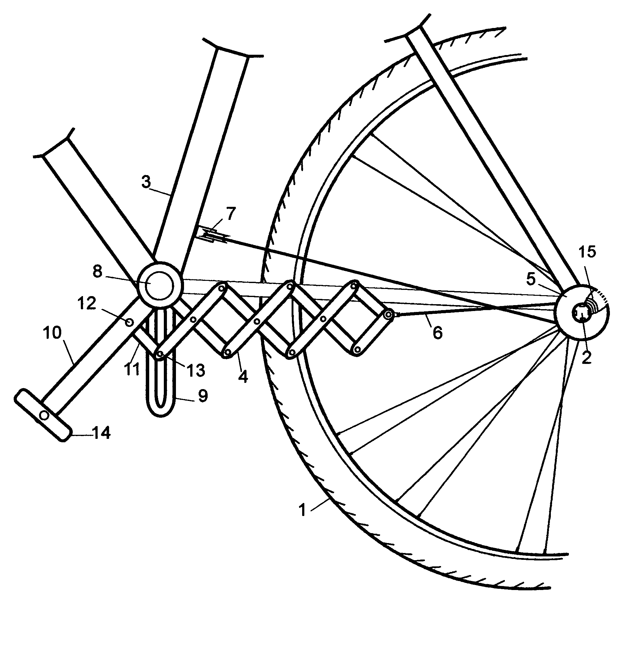
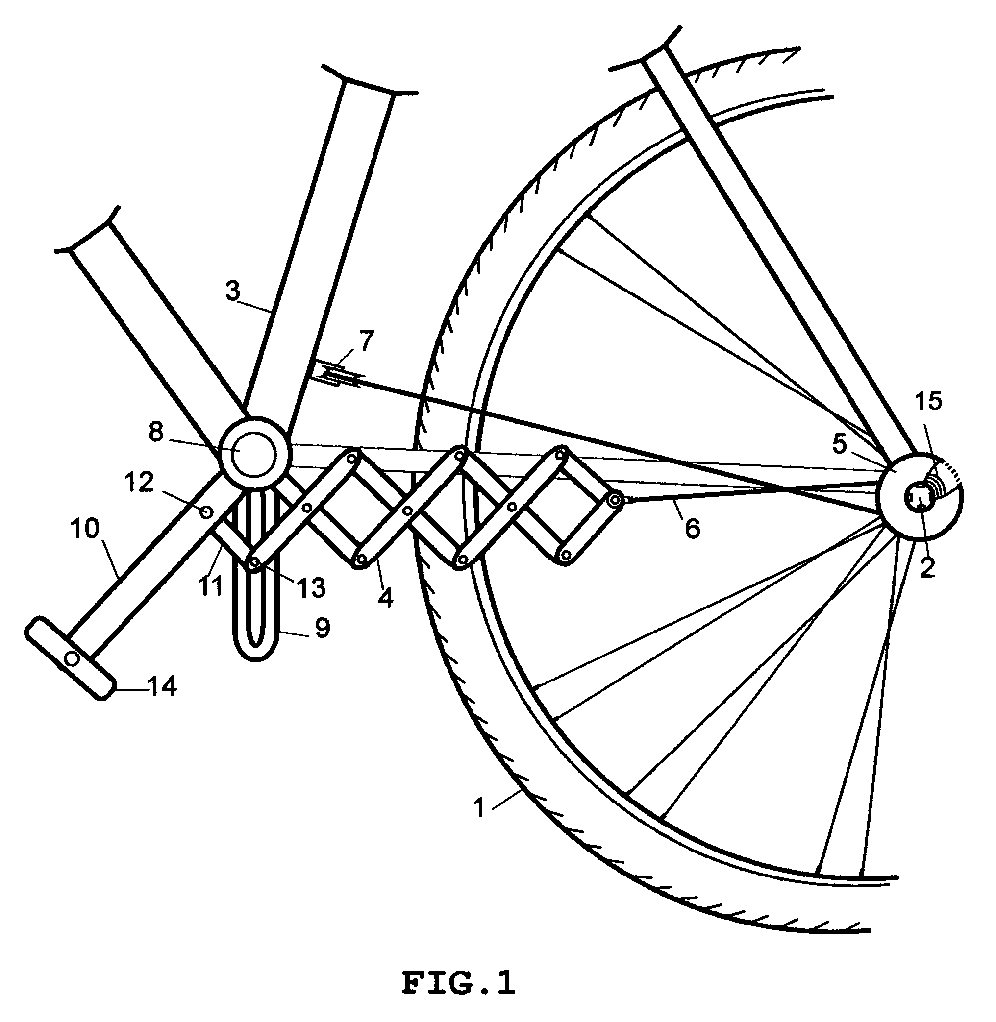
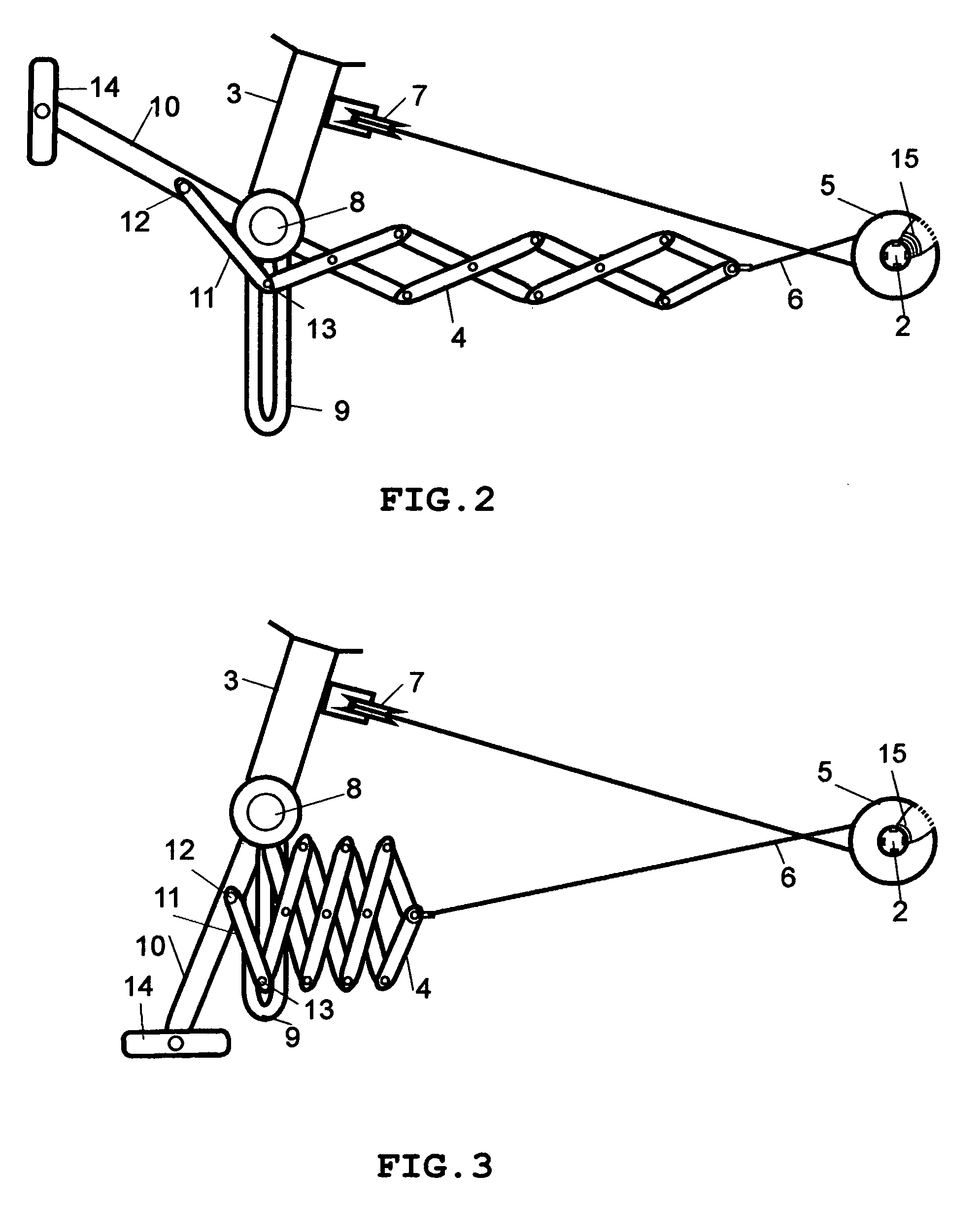
[0014] Referring now to the drawings and in particular to FIG. 1, one embodiment of the power pedal is illustrated on a bicycle. The omission of the detail definition and description of the bicycle does not preclude from the understanding of preferred embodiments. However, for the purpose of the present invention embodiments, a cycle-type vehicle includes at least two wheels from which one is a driven wheel 1 with an axle 2 and a frame 3. The frame 3 alternatively has supports or struts commonly provided on bicycles, or other desired structural members, etc.

[0015] The preferred embodiments of the present invention include two scissor-type pedal assembly 4 positioned in a mirror image on both sides of the frame, although the illustrations refer mostly to one. The pedal assembly 4 is pivotally mounted on a stationary shaft 8 on both sides of the frame 3, more or less in the vicinity where the conventional pedals are mounted. Pedal assembly units are defined by pivotally interconnecte...


PUM


Abstract

A novel drive mechanism for a bicycle, featuring a scissor assembly defined by plurality of arms pivotally interconnected in an expandable sequence. The scissor assembly is attached pivotally to a frame on both sides and via a rigid slot attached pivotally to pedal cranks whereby permitting cranks oscillating motion. The cranks reciprocal oscillating motion is transferred by the assembly into a linear pulling force connected to a drive wheel axle, equipped with a freewheeling reel, by a flexible ligament spiraled in the reel. The efficiency of assembly's power transfer kinetics lessens required human force, in addition, the speed is substantially increased because the cranks motion is confined to the most efficient frontal segment of the 360-degree orbit whereby eliminating back-upward segment of the circular motion pedals.

Description

BACKGROUND OF THE INVENTION [0001] This invention relates to a power-transmitting device for a vehicle. More specifically, the present invention relates to a new drive mechanism for transferring power from the pedals to the rear wheel of a bicycle. [0002] The use of bicycle drive mechanisms is well known in the prior art. Bicycle drive mechanisms devised and utilized are known to consist of familiar, expected and obvious structural configurations. The prior art is crowded with numerous designs which have been developed for the fulfillment of countless objectives and requirements. [0003] Known prior art bicycle drive mechanisms include U.S. Pat. No. 4,564,206; U.S. Pat. No. 6,749,211; U.S. Pat. No. 6,764,089; U.S. Pat. No. 6,779,807; and U.S. Pat. No. 6,783,139; [0004] The objective of a conventional bicycle pedal configuration is to exert a pulling force to the endless chain by circular motion of the pedal lever. Pedals work on lever principle wherein the net lever arm is the differ...

Claims


Application Information

Patent Timeline
Patent Type & Authority Applications(United States)
IPC IPC(8): B62M5/00B62M1/00
CPCB62M1/28B62M1/32B62M5/00
Inventor SUSKO, RUDOLF
Owner SUSKO RUDOLF
Why Eureka
Try Eureka