
Methods and devices for determining the linearity of signals

Active Publication Date: 2006-05-25
LOCKHEED MARTIN CORP
View PDF35 Cites 4 Cited by
  • Summary
  • Abstract
  • Description
  • Claims
  • Application Information

AI Technical Summary

Benefits of technology

[0010] Because, as explained in more detail below, it is not necessary to store the same amount of frequency information as conventional techniques, the memory capacity needed to carry out linearity tests using the present invention is reduced.

Problems solved by technology

Unfortunately, conventional systems that implement this technique require a significant amount of memory and, relatively speaking, a long period of time to determine the linearity of a signal.
The time period which elapses between the detection and storage of the components and the subsequent calculation of a slope is unacceptable.
In addition, in order to store all of the components, a large amount of memory is required.
This is also unacceptable.

Method used


Image

  • Methods and devices for determining the linearity of signals
  • Methods and devices for determining the linearity of signals
  • Methods and devices for determining the linearity of signals

Examples


Embodiment Construction

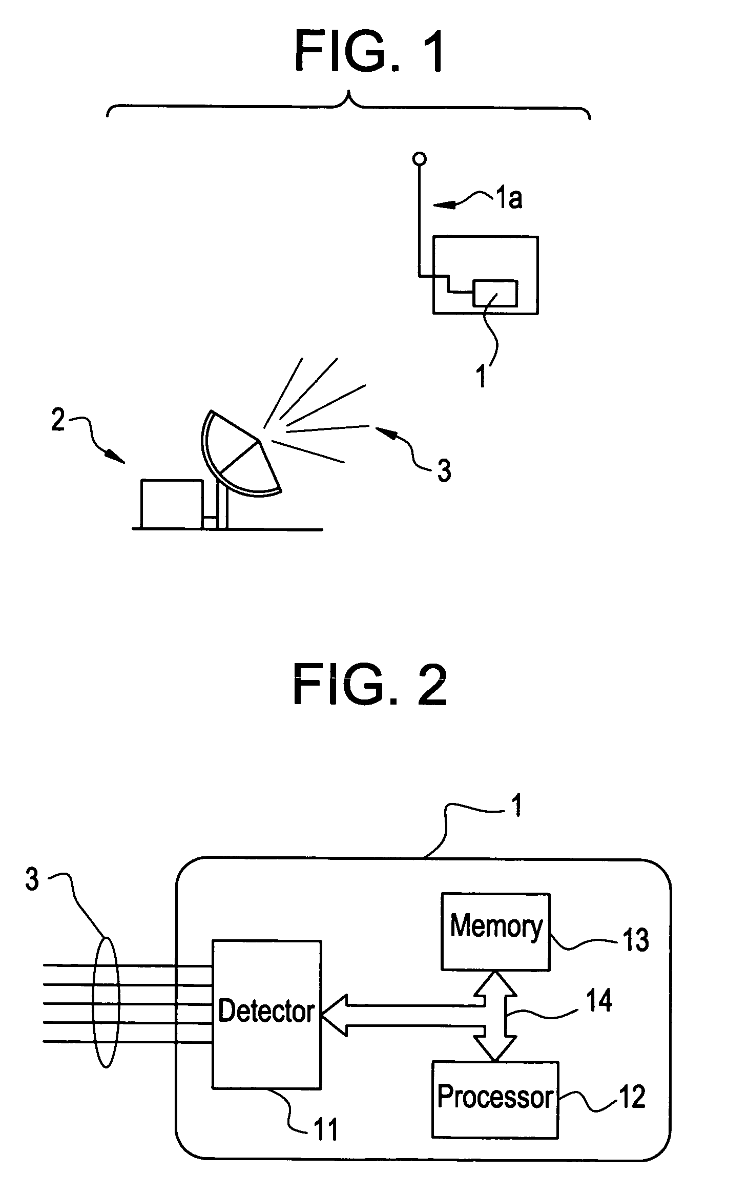
[0017] Referring now to FIG. 1, there is shown a receiver 1 with antenna 1b operable to detect a pulse of a transmitted signal 3 emitted from a source or sources 2 (e.g., radar).

[0018] In more detail, yet still simplified, a drawing of receiver 1 is shown in FIG. 2. As shown in FIG. 2, the receiver 1 may comprise a detector 11, processor 12, and memory section 13, all interconnected via a data and signaling bus 14. While shown as three separate elements, it should be understood that the detector 11, processor 12 and memory section 13 may be combined into fewer elements or further broken down into additional elements. For example, the processor 12 and memory 13 may be combined and / or the memory 13 may be further broken down into additional memory sections. In addition, it should be noted that the detector 11 may be a separate unit altogether, distinct from the processor 12 and memory section 13. The receiver 11 may be a satellite, airborne, ground or sea-based receiver.

[0019] The p...


PUM


Abstract

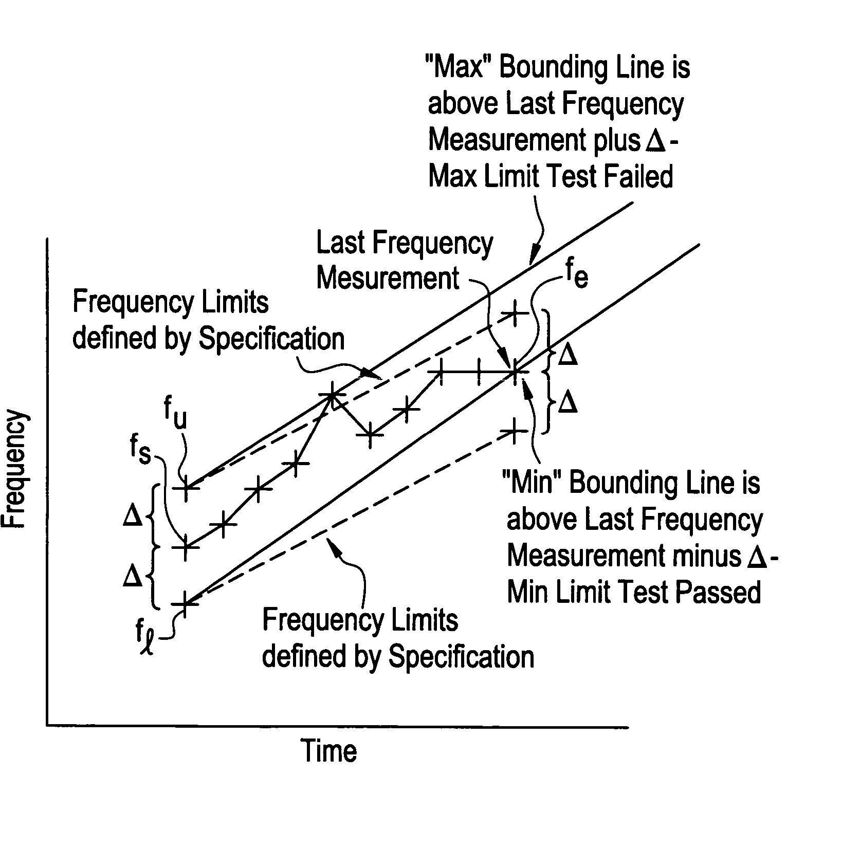
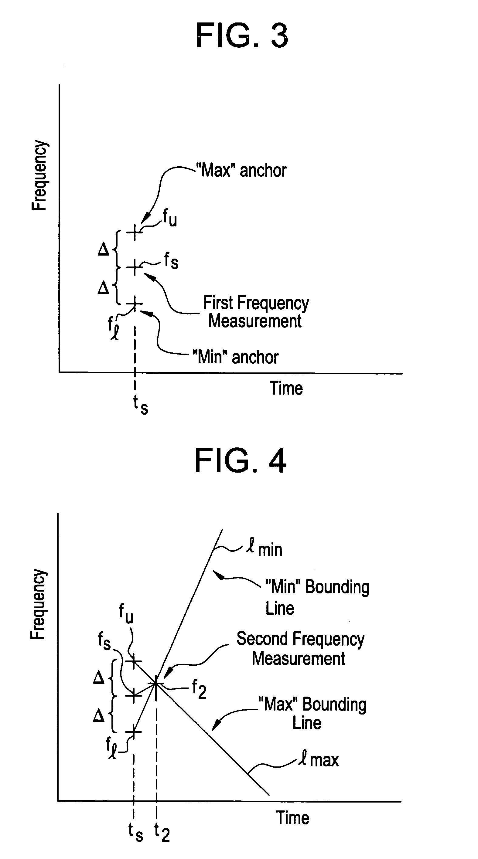
The time it takes to determine whether a signal is a linear or non-linear frequency modulated (FM) signal is significantly reduced by continuously updating upper and lower frequency-related bounds (e.g., slopes) used in determining whether a signal is a linear or non-linear FM signal in real-time. The techniques provided by the present invention also require substantially less memory to determine whether a signal is a linear or non-linear FM signal.

Description

GOVERNMENT INTERESTS [0001] This invention may have been made with U.S. Government support under Contract No. ______. The U.S. Government may have certain rights in this invention.BACKGROUND OF THE INVENTION [0002] There exists techniques capable of determining whether a signal is a “linear” or “non-linear” frequency modulated (FM) signal. One technique requires the detection of a first or start frequency and an end frequency of a signal. The slope of a line connecting these two frequencies is then used to determine the linearity of the signal. [0003] A signal is considered to be a linear FM signal when, over a given time period, frequency components of the signal fall within a lower or upper bound slope. When this does not occur, the signal is said to be a non-linear FM signal. [0004] Unfortunately, conventional systems that implement this technique require a significant amount of memory and, relatively speaking, a long period of time to determine the linearity of a signal. [0005] ...

Claims


Application Information

Patent Timeline
IPC IPC(8): G01S7/40
CPCG01R23/20G01S7/021
Inventor MOCH, THOMAS A.
Owner LOCKHEED MARTIN CORP
Learn More