Sampling circuit

a circuit and sampling technology, applied in the field of sampling circuits, can solve the problems of complex circuits and inability to carry out exact analyses, and achieve the effect of reducing inspection time and reducing operation tim

Inactive Publication Date: 2012-07-24
SOCIONEXT INC
View PDF8 Cites 0 Cited by
  • Summary
  • Abstract
  • Description
  • Claims
  • Application Information

AI Technical Summary

Benefits of technology

[0042]In the sampling circuit according to the present invention, since in inspecting the non-linearity errors in an AD converter or a DA converter, the sampling processing for sampling the inputted one cycle digital data at a constant period, and the addition and outputting processing for adding the sampled digital data for the same input code and successively outputting the added result are carried out concurrently with each other, the operation time can be reduced, and the inspection time can be reduced to a great extent.
[0043]In the sampling circuit according to the present invention, since the sampled data is not stored as it is for the same input code into the data storing means but the result of taking a mean operation thereof is only stored therein, a memory capacity that would be required for storing sampled data can be reduced to a great extent.

Problems solved by technology

When analyzing the waveform which is outputted from an AD converter or a DA converter, it is not possible to carry out an exact analysis if the noises included in the waveforms are removed.
In addition, when outputs of plural AD converters or plural DA converters are switched to be outputted to a signal line, the low pass filters or the filters also have to be provided in plural, thereby resulting in complicated circuits.

Method used


Image

  • Sampling circuit
  • Sampling circuit
  • Sampling circuit

Examples


first embodiment

[0066]Hereinafter, a sampling circuit according to a first embodiment of the present invention will be described with reference to the drawings.

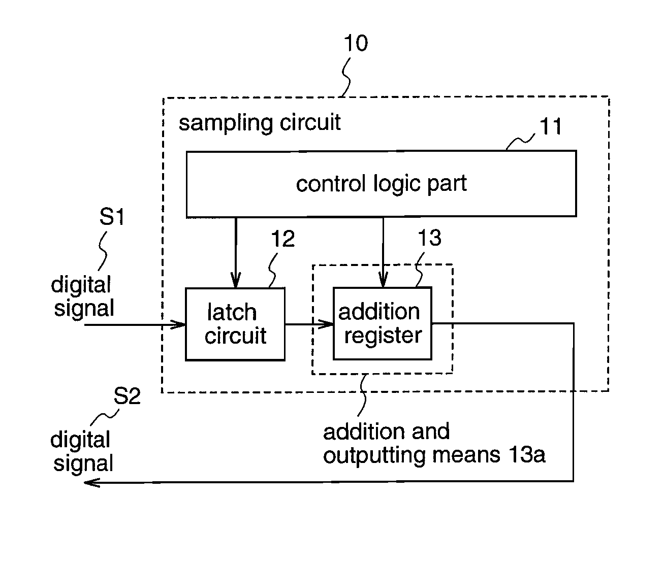
[0067]FIG. 1 is a diagram illustrating a construction of a sampling circuit 10 in an AD converter or a DA converter according to a first embodiment of the present invention.

[0068]The sampling circuit 10 according to this first embodiment is provided with a control logic unit (control means) 11, a latch circuit (constituting a sampling means) 12, and an addition and outputting means 13a.

[0069]The latch circuit 12 receives one cycle digital signal S1 which is outputted from the device to be measured as an input and samples the digital signal S1 at a constant period.

[0070]The addition and outputting means 13a comprises an addition resister (adder circuit), and adds the digital data which was sampled by the latch circuit 12 for a predetermined addition number for the same input code, and outputs the added values successively.

[0071]The control l...

second embodiment

[0080]Hereinafter, a sampling circuit according to a second embodiment of the present invention will be described with reference to the drawings.

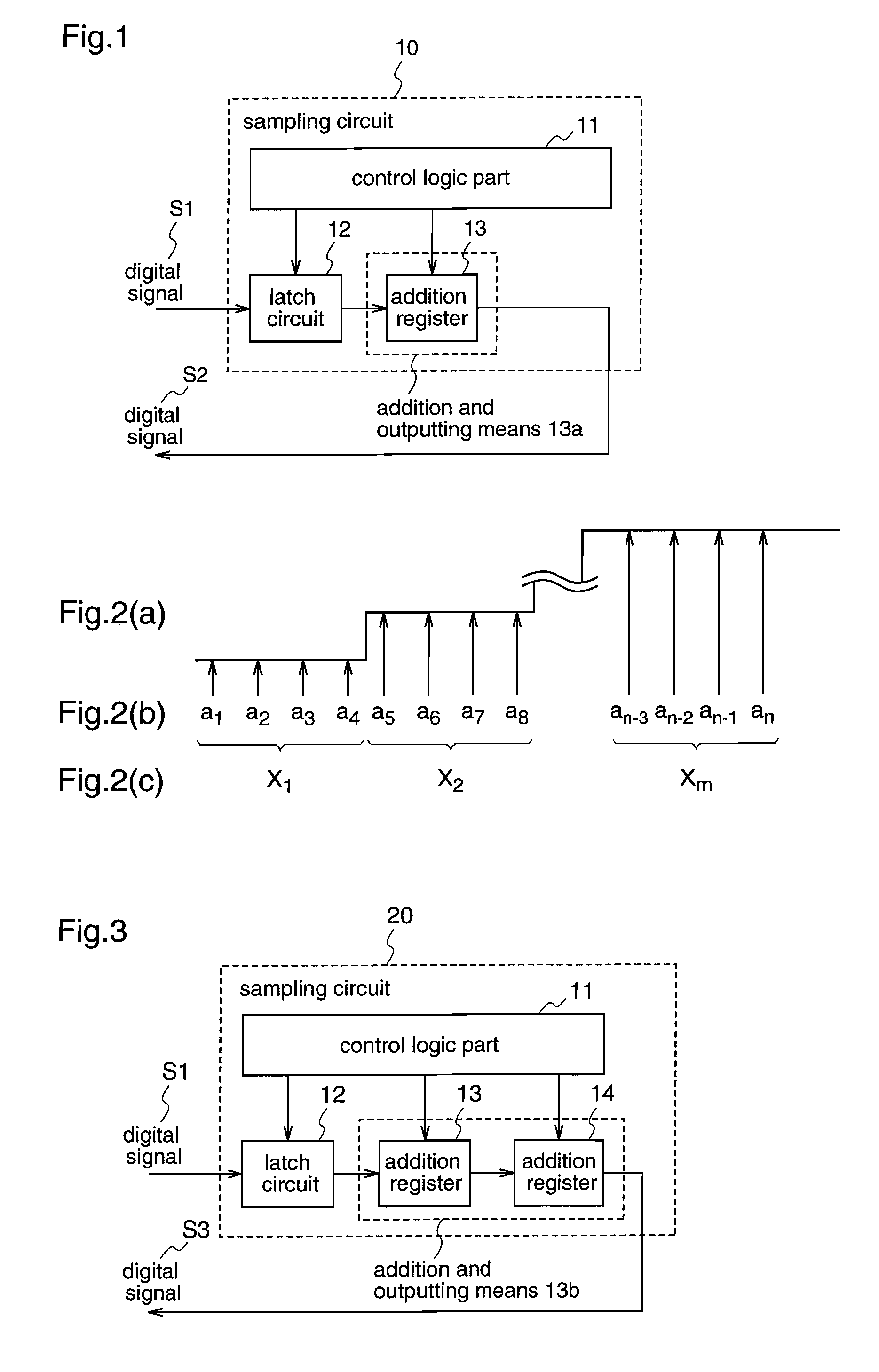
[0081]FIG. 3 is a diagram illustrating a construction of a sampling circuit 20 in an AD converter or a DA converter according to the second embodiment. In FIG. 3, the same reference numerals as used in FIG. 1 are added to the same constituents.

[0082]The sampling circuit of this second embodiment is provided with a control logic part 11, a latch circuit 12, and an addition and outputting means 13b.

[0083]The addition and outputting means 13b comprises two adder circuits 13 and 14, which adds the input data for a predetermined addition number, and outputs the added values, respectively.

[0084]The addition register 14 adds the addition values which are inputted from the addition register 13 for a predetermined addition number, and output the added value.

[0085]In addition, the control logic part 11 has addition number setting means for setting t...

third embodiment

[0104]Hereinafter, a sampling circuit according to a third embodiment of the present invention will be described with reference to the drawings.

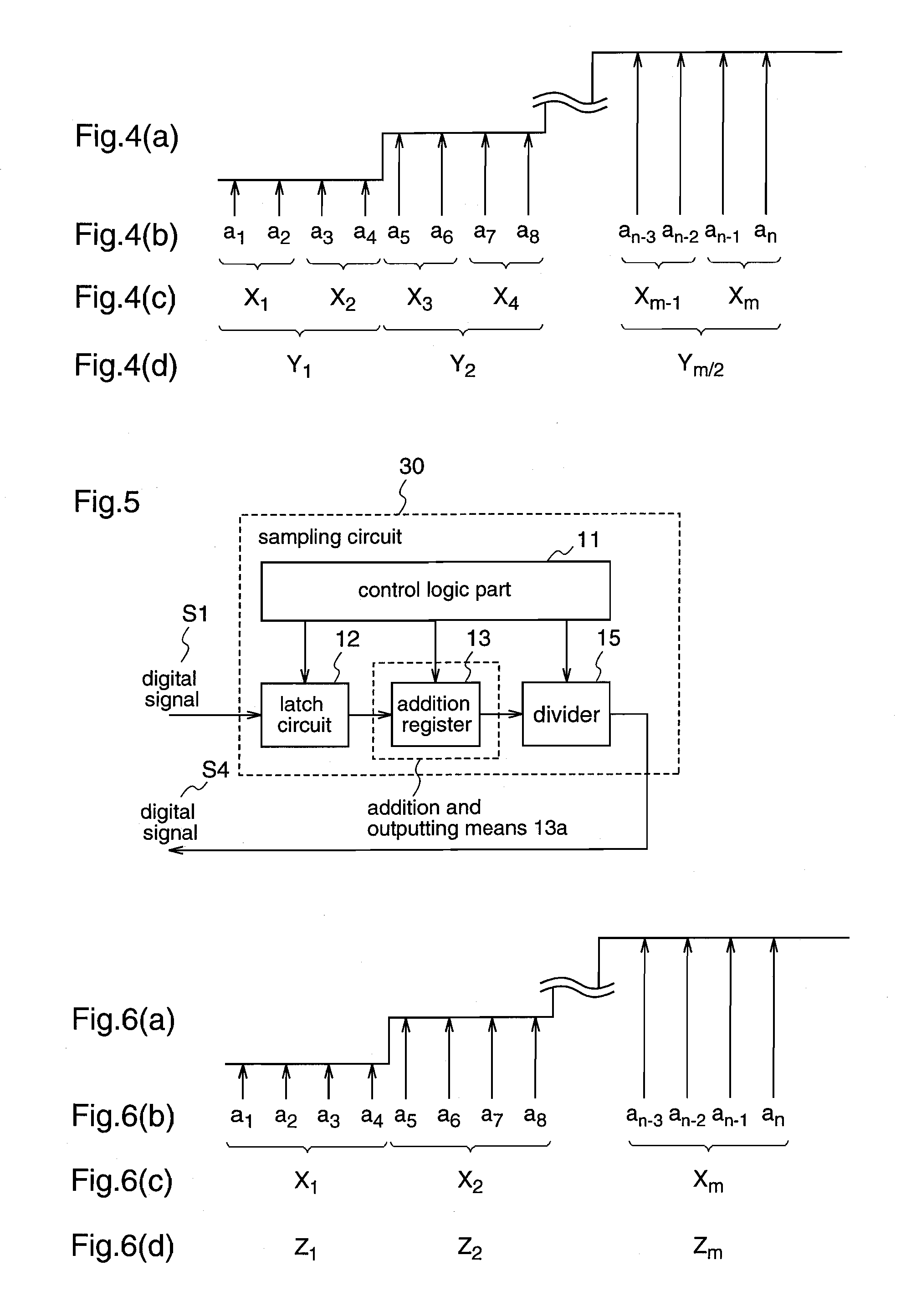
[0105]FIG. 5 is a diagram illustrating a construction of a sampling circuit 30 according to the third embodiment. In FIG. 5, the same reference numerals as used in FIG. 1 are added to the same constituents.

[0106]The sampling circuit 30 of this third embodiment is provided with a control logic unit 11, a latch circuit 12, an addition and outputting means 13a, and a divider (a division and outputting means) 15. In addition, the addition and outputting means 13a comprises an addition register 13.

[0107]The divider 15 divides the added values which are outputted from the addition register 13 by respective predetermined divisor and outputs the divided values.

[0108]Here, the control logic unit 11 includes an addition number setting means (not shown) for setting an addition number for the digital data which are added together by the addition registe...


PUM


Abstract

A sampling circuit includes a latch circuit which latches the digital signal S1 at a constant period, an addition register which adds the sampled data for the same input code, a divider which divides the added value by a predetermined divisor, a digital memory which stores the divided value and outputs it at an arbitrary timing for a predetermined reading out number, an operator which operates the output data from the digital memory in accordance with a previously set algorithm, a judgment circuit which judges the operation result with a predetermined judgment criterion, and a control logic part which controls such that the addition and outputting processing by the addition register and the division and outputting processing by the divider are carried out concurrently with the sampling processing by the latch circuit. This sampling circuit in an AD converter or a DA converter can reduce inspection cost.

Description

TECHNICAL FIELD[0001]The present invention relates to a sampling circuit in an AD converter or a DA converter.BACKGROUND ART[0002]When analyzing the waveform which is outputted from an AD converter or a DA converter, it is not possible to carry out an exact analysis if the noises included in the waveforms are removed. As sources generating noises, there are noises which are mixed into from the power supply or ground, or noises which are possessed by an LSI tester or a measuring apparatus itself.[0003]In order to remove noises, there is a method of performing a filtering processing with using a low pass filter for analog signals while using a filter for digital signals. In these methods, however, it is required to appropriately select a low pass filter or a filter in accordance with an AD converter or a DA converter. In addition, when outputs of plural AD converters or plural DA converters are switched to be outputted to a signal line, the low pass filters or the filters also have to...

Claims


Application Information

Patent Timeline
Patent Type & Authority Patents(United States)
IPC IPC(8): G06F7/38
CPCH03M1/0658H03M1/12H03M1/66
Inventor IDE, YUJI
Owner SOCIONEXT INC
Why Eureka
Try Eureka