Optical film, polarizing plate, liquid crystal cell, liquid crystal display device, image display device and method of manufacturing an optical film
a technology of optical film and polarizing plate, which is applied in the field of optical film, can solve the problems of birefringent retardation and optical characteristics, and achieve the effect of limiting the variation of the retardation of the birefringent layer and good adhesive power
- Summary
- Abstract
- Description
- Claims
- Application Information
AI Technical Summary
Benefits of technology
Problems solved by technology
Method used
Image
Examples
example 1
[0110] A self-emulsifying, water-dispersible polyurethane resin (Linear polyurethane having a bisphenol A framework, trade name Bondtighter HUX320, manufactured by Asahi Electrochemicals K.K.) was mixed with a mixture as a solvent (dispersion medium) of water and isopropyl alcohol (weight ratio of 1:1) to prepare a 10 wt. % solution (dispersion medium) of a polyurethane-based resin, which was in turn coated on the entire surface of a triacetylcellulose film by gravure coating. Then, it was subjected to a heat treatment at a temperature of 120° C. for 10 minutes. Thus, a transparent, flat and smooth film having an adhesive layer and having a thickness of about 80 μm was obtained. The thickness of the adhesive layer was 3 μm.
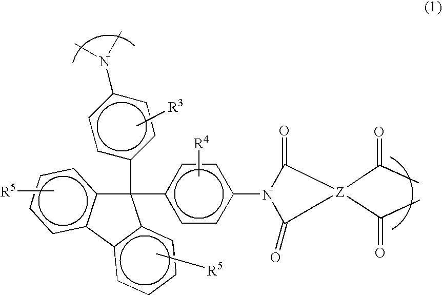
[0111] Then, polyimide of Δnd≈0.04, which was synthesized from 2,2-bis(3,4-dicarboxyphenyl)hexafluoropropane≈6FDA and 2,2′-bis(trifluoromethyl)-4,4′-diaminobiphenyl≈PFMB≈TFMB, was dissolved by using cyclohexanone as a solvent so as to prepare a 23 wt. % solution ...
example 2
[0112] A polyester-based polyurethane resin containing aromatic polyester as a main component (trade name VYRON UR-1400, manufactured by Toyobo Co., Ltd.) was dissolved by using methylisobutylketone as a solvent so as to prepare a 5 wt. % solution of a polyester-based polyurethane resin, and the solution was coated on triacetylcellulose by gravure coating in the same manner as Example 1. Then, it was subjected to a heat treatment at a temperature of 120° C. for 10 minutes. Thus, a transparent, flat and smooth film having an adhesive layer was obtained. The thickness of the adhesive layer was 1 μm. Then, a perfect transparent optical film having a birefringent layer was obtained in the same manner as Example 1 except that the film obtained in this Example was used. In the thus obtained optical film, the thickness of the birefringent layer was 6 μm, the average value of Rth was 240 nm, and the average value of And was 60 nm. The variation of Rth was within plus or minus 3 nm, and the ...
example 3
[0113] A 5 wt. % solution of a polyester-based polyurethane resin used in the Example 2 was coated on a norbornene-based, transparent polymer film (trade name ARTON, manufactured by JSR Corporation) by gravure coating. Then, it was subjected to a heat treatment at a temperature of 120° C. for 10 minutes. Thus, a transparent, flat and smooth film having an adhesive layer and having a thickness of about 80 μm was obtained. The thickness of the adhesive layer was 0.5 μm. Then, a perfect transparent optical film having a birefringent layer was obtained in the same manner as Example 1 except that the film obtained in this Example was used. In the thus obtained optical film, the thickness of the birefringent layer was 6 μm, the average value of Rth was 240 nm, and the average value of Δnd was 60 nm.
[0114] The variation of Rth was within plus or minus 3 nm, and the variation of And was within plus or minus 2 nm. The birefringent layer had an optically biaxial property of nx>ny>nz.
PUM
| Property | Measurement | Unit |
|---|---|---|
| thickness | aaaaa | aaaaa |
| thickness | aaaaa | aaaaa |
| thickness | aaaaa | aaaaa |
Abstract
Description
Claims
Application Information
 - R&D Engineer
- R&D Manager
- IP Professional
- Industry Leading Data Capabilities
- Powerful AI technology
- Patent DNA Extraction
Browse by: Latest US Patents, China's latest patents, Technical Efficacy Thesaurus, Application Domain, Technology Topic.
© 2024 PatSnap. All rights reserved.Legal|Privacy policy|Modern Slavery Act Transparency Statement|Sitemap


