Thermal barrier coating for turbine bucket platform side faces and methods of application

a technology of thermal barrier coating and bucket platform, which is applied in the direction of superimposed coating process, machines/engines, mechanical equipment, etc., can solve the problems of increasing stress on bucket platform, oxidation, creep cracking and low cycle fatigue, and exacerbated potential distress on bucket platform

Inactive Publication Date: 2006-05-25
GENERAL ELECTRIC CO
View PDF2 Cites 19 Cited by
  • Summary
  • Abstract
  • Description
  • Claims
  • Application Information

AI Technical Summary

Problems solved by technology

As gas path temperatures have increased, bucket platforms have increasingly exhibited stress including oxidation, creep and low cycle fatigue cracking.
This exacerbates the potential distress on bucket platforms as the platforms run even hotter.
The firin

Method used


Image

  • Thermal barrier coating for turbine bucket platform side faces and methods of application
  • Thermal barrier coating for turbine bucket platform side faces and methods of application

Examples


Embodiment Construction

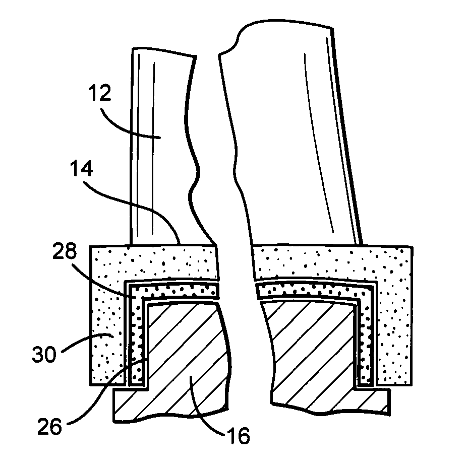
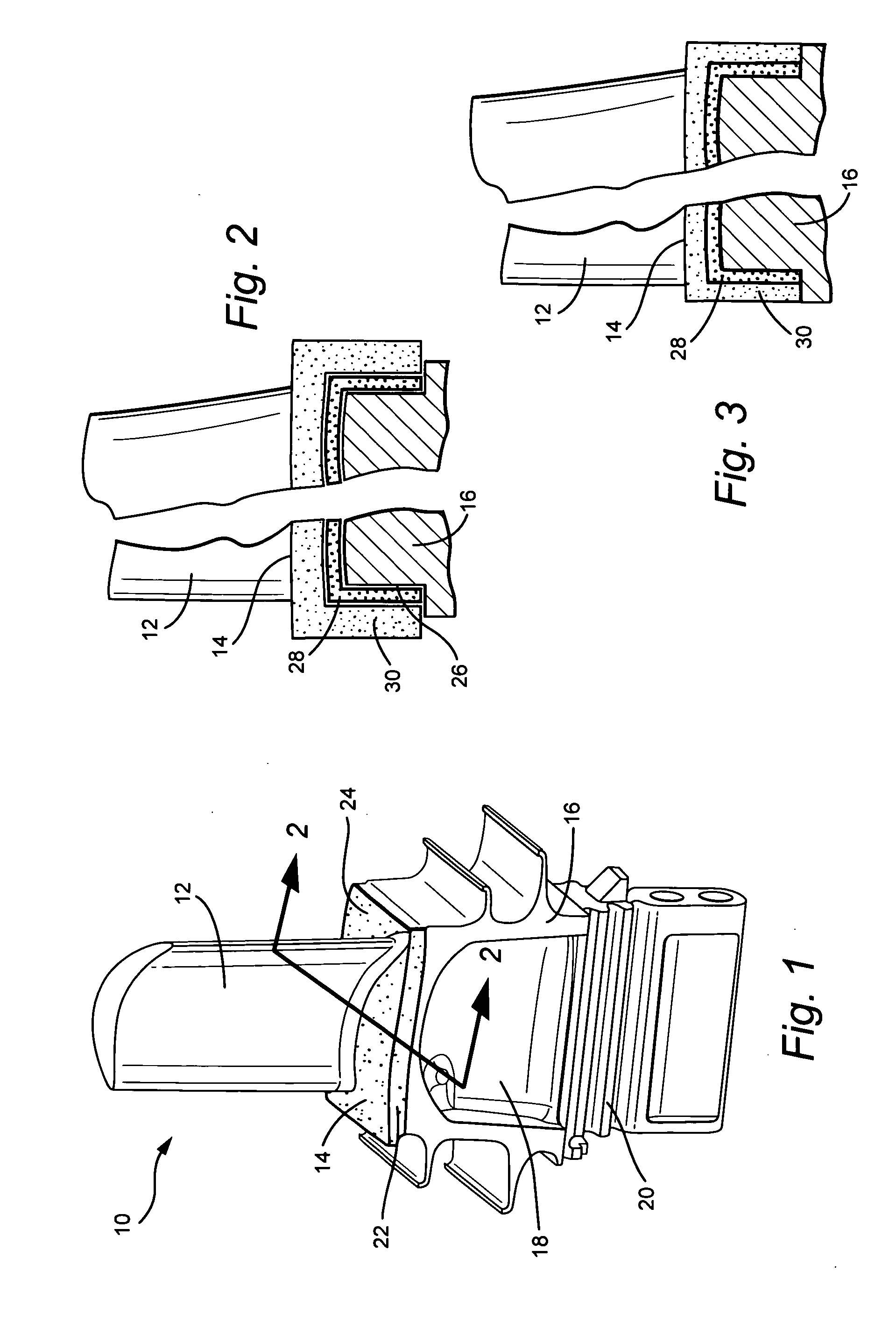
[0009] Referring now to the drawing figures, particularly to FIG. 1, there is illustrated a turbine bucket generally designated 10 having an airfoil 12, a platform 14 and a root portion 16 including a shank 18 and dovetail 20. It will be appreciated that the turbine bucket 10 is typically arranged in an annular array of like turbine buckets on the rotor wheel of a turbine with the side faces 22 of the platform 14 generally circumferentially registering with corresponding side faces of circumferentially adjacent bucket platforms. Typically, the bucket surfaces are formed of bare metal.

[0010] While platform surfaces such as the platform surface 24 illustrated in FIG. 1 have previously received a thermal barrier coating, the side faces 22 of the platform which lie in circumferential registration with side faces of adjacent bucket platforms, according to applicant's knowledge, have not previously been provided with a thermal barrier coating. Thermal barrier coatings per se have been us...


PUM

PropertyMeasurementUnit
Thicknessaaaaaaaaaa

Abstract

Grooves are formed along portions of the side edges of a turbine bucket platform and open through the side edges of the surface of the platform exposed to the hot gas path of the turbine. A bond coat is applied to the groove followed by a thermal barrier coating which is preferably plasma sprayed onto the bond coat. The thermal barrier coating thickness protects the coating beyond the surface of the bare metal of the platform side and is then abraded or ground to lie flush with the bare metal surface. Thus, the side faces of the platform have a thermal barrier coating to reduce oxidation.

Description

BACKGROUND OF THE INVENTION [0001] The present invention relates to a thermal barrier coating applied to side faces of the platform of a turbine bucket and methods of application. [0002] Over the years, gas turbines have trended towards increased inlet firing temperatures to improve output and engine efficiencies. As gas path temperatures have increased, bucket platforms have increasingly exhibited stress including oxidation, creep and low cycle fatigue cracking. In certain turbines using closed circuit steam cooling in the first two stages of buckets and nozzles, inlet profiles have become such that the platforms are staying close to peak inlet temperatures for the blade row. This exacerbates the potential distress on bucket platforms as the platforms run even hotter. [0003] In many older turbine designs, the bucket platforms did not require a coating to prevent oxidation distress due to firing temperatures. The firing temperatures were not sufficiently high to cause substantial di...

Claims


Application Information

Patent Timeline
IPC IPC(8): F01D11/00
CPCC23C30/00F01D5/288C23C28/3215C23C28/3455
Inventor ITZEL, GARY MICHAELJACALA, ARIEL CAESAR-PREPENA
Owner GENERAL ELECTRIC CO
Why Eureka
Try Eureka