Cor adjustment device

a technology of adjustment device and cor, which is applied in the field of golf clubs, can solve the problems of rotational displacement of engagement members, decrease of club head flexibility, and decrease of club head cor, so as to reduce the flexibility of the club head and reduce the cor of the club head

Active Publication Date: 2006-05-25
ACUSHNET CO
View PDF37 Cites 295 Cited by
  • Summary
  • Abstract
  • Description
  • Claims
  • Application Information

AI Technical Summary

Benefits of technology

[0013] The bias member can be provided in a variety of designs. For example, the engagement member may contain an internal, threaded orifice and the adjustment member may include an outer surface at least a portion of which is threaded for operative engagement with the threaded orifice. With the engagement member constrained against rotational movement, rotation of the adjustment member causes a vertical displacement of the engagement member, changing the location at which the engagement member contacts the club face. As the contact location is adjusted vertically upwardly along the inwardly sloping face (due to the club head loft angle), the force exerted by the engagement member against the face interior surface increases. Increasing the force exerted against the interior surface of the club face decreases the flexibility of the club face and decreases the COR of the club head. The retaining wall may be configured to constrain the engagement member against rotational movement.

Problems solved by technology

Increasing the force exerted against the interior surface of the club face decreases the flexibility of the club face and decreases the COR of the club head.
However, in this embodiment, the engagement member is constrained against vertical movement such that rotation of the adjustment member causes a rotational displacement of the engagement member.

Method used


Image

  • Cor adjustment device
  • Cor adjustment device
  • Cor adjustment device

Examples


first embodiment

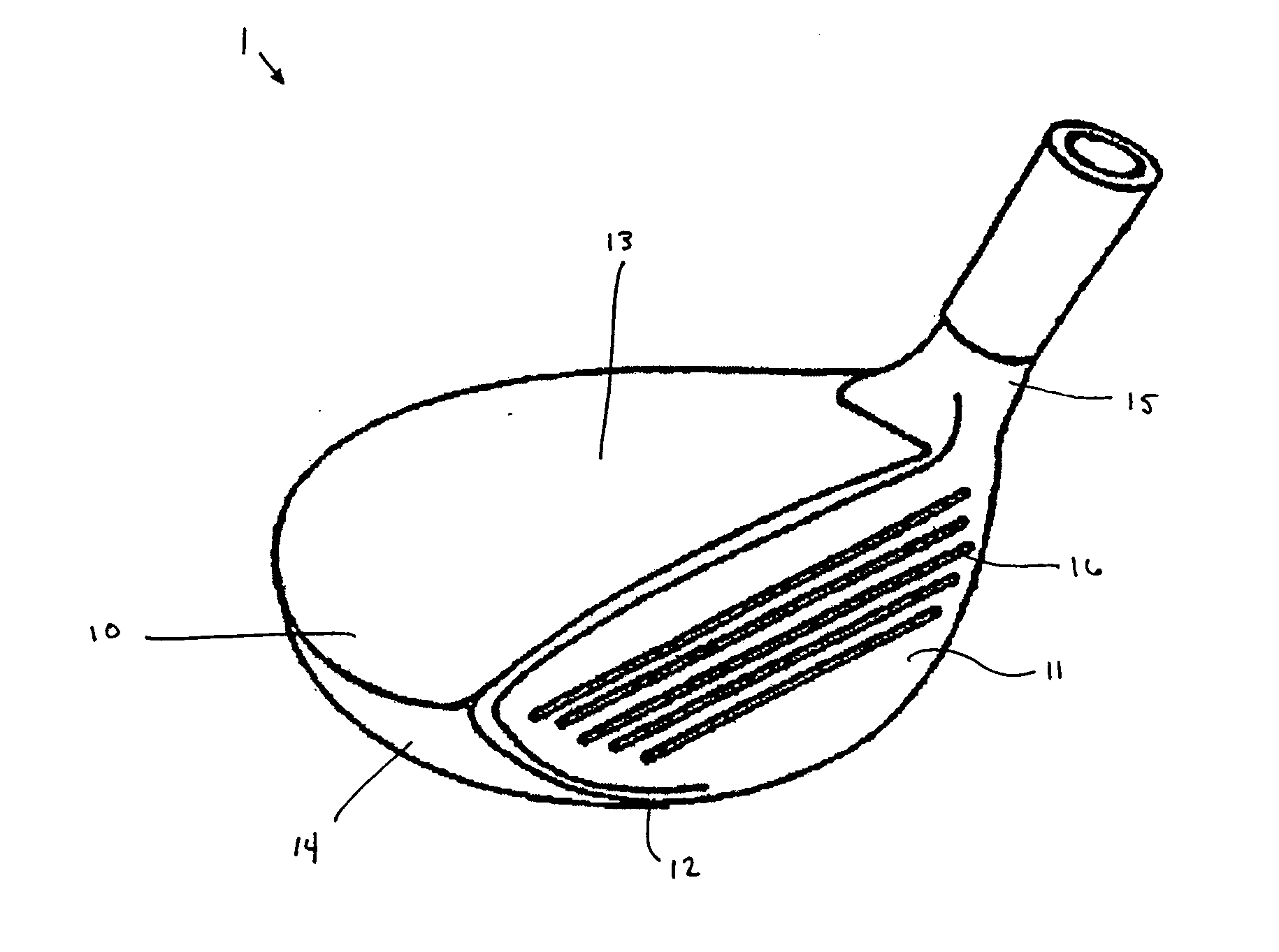
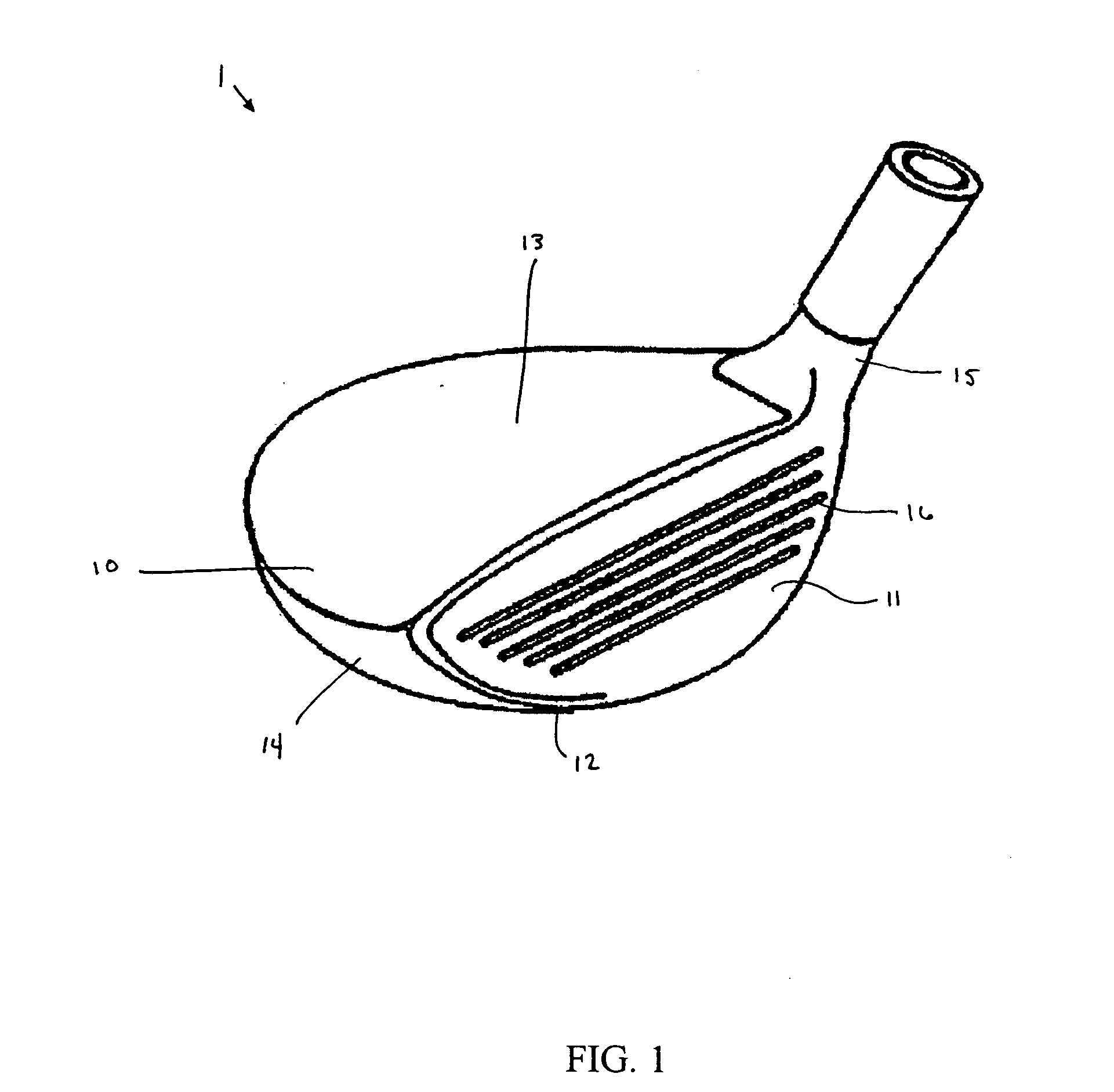
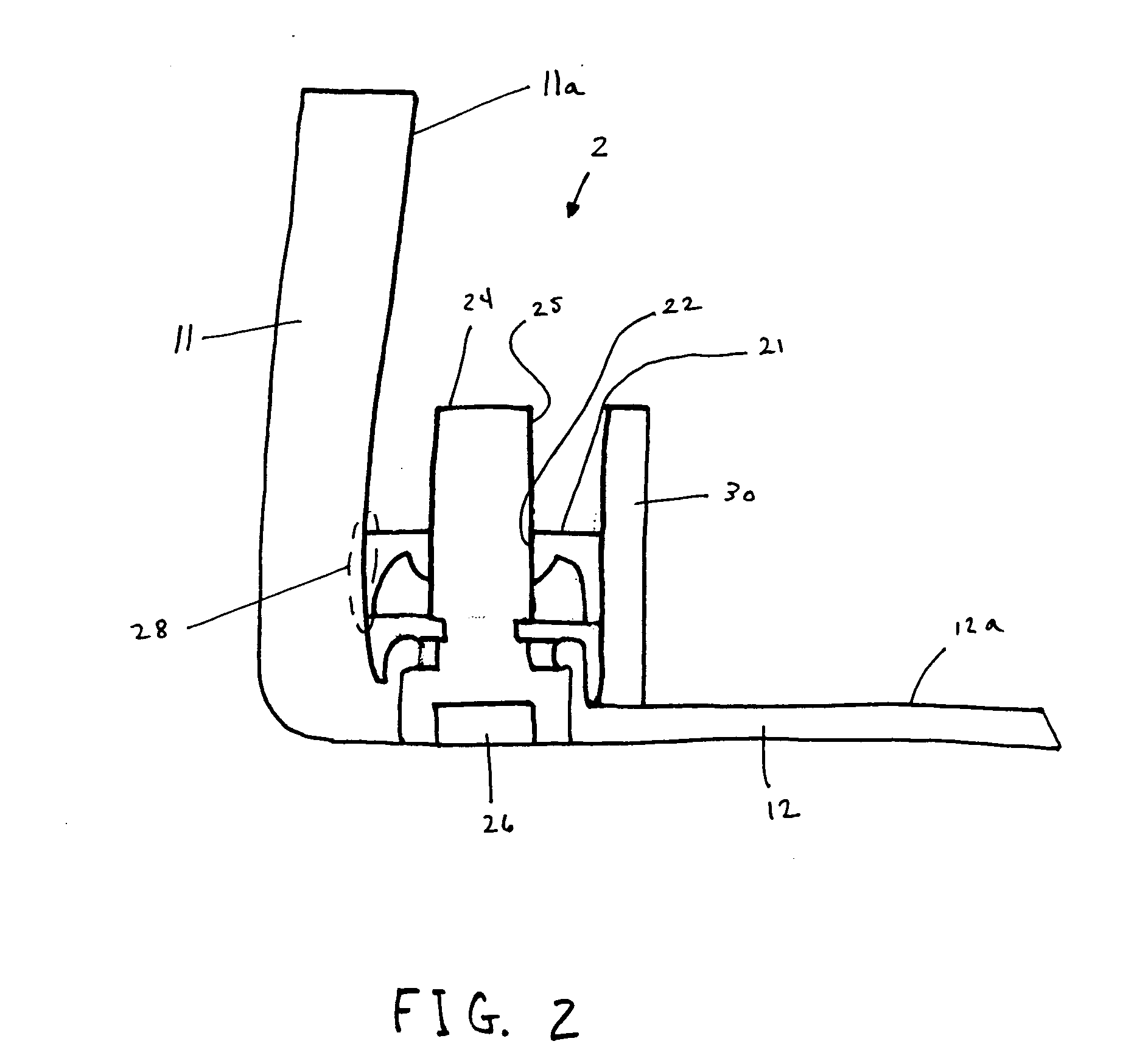
[0031] In a first embodiment, the bias member 2 includes an engagement member 21 in contact with the face interior surface 11a at the contact location 28, and an adjustment member 24 operatively coupled to the engagement member 21. The engagement member 21 contains an internal, threaded orifice 22. The adjustment member 24 includes an outer surface 25 at least a portion of which is threaded for operative engagement with the threaded orifice 22 of the engagement member 21. The engagement member 21 is constrained against rotational movement such that rotation of the adjustment member 24 causes a vertical displacement of the engagement member 24, changing the contact location 28. The adjustment member 24 includes a portion 26 that may be engaged with a tool in known manner to rotate the adjustment member 24. For example, the engagement portion 26 may be shaped for mating engagement with a hex head wrench. Preferably, the adjustment member 21 is operatively accessible from outside the c...

third embodiment

[0036] In a third embodiment, shown in FIG. 4, the bias member 2 includes an engagement member 21 in contact with the face interior surface 11a at the contact location 28, an adjustment member 24 in contact with the engagement member 21, and a retaining wall 30. The engagement member 21 is rotatively coupled to the retaining wall 30 such as via a pin 32. Preferably, one end of the engagement member 21 is coupled to the retaining wall 30 in cantilever fashion. The other end is curved, providing numerous points at which it may contact the face interior surface 11a. The sole 12 includes a threaded orifice 12b, with which the adjustment member 24 is operatively engaged. An inner end 24a of the adjustment member 24 contacts the engagement member 21. Due to the loft angle, the face 11 exerts pressure against the engagement member 21 that tends to force it downward into the adjustment member 24. Rotation of the adjustment member 24 results in vertical displacement thereof, causing rotation...


PUM


Abstract

A golf club head with a variable coefficient of restitution is disclosed and claimed. The club head includes a bias member that contacts and exerts a force against the interior surface of the face. The force exerted against the interior of the face lessens the face flexibility, and decreases the club head coefficient of restitution. The bias member can be adjusted from outside the club head, allowing the manufacturer to precisely adjust the club head coefficient of restitution.

Description

CROSS-REFERENCE TO RELATED APPLICATIONS [0001] This application is a continuation-in-part of U.S. patent application Ser. No. 10 / 992,073 filed on Nov. 19, 2004, now pending, which is incorporated herein by reference in its entirety.BACKGROUND OF THE INVENTION [0002] 1. Field of the Invention [0003] The present invention relates to a golf club, and, more particularly, the present invention relates to a golf club with a coefficient of restitution adjustment device. [0004] 2. Description of the Related Art [0005] Golf club heads come in many different forms and makes, such as wood- or metal-type, iron-type (including wedge-type club heads), utility- or specialty-type, and putter-type. Each of these styles has a prescribed function and make-up. The present invention relates to hollow golf club heads, such as wood-type and utility-type (generally referred to herein as wood-type golf clubs). [0006] Wood-type type golf club heads generally include a front or striking face, a crown, a sole,...

Claims


Application Information

Patent Timeline
Patent Type & Authority Applications(United States)
IPC IPC(8): A63B53/04
CPCA63B49/06A63B53/0466A63B53/06A63B53/08A63B2053/0433A63B2053/0491A63B60/00A63B60/52A63B53/0433A63B53/0454
Inventor POYNOR, RAYMOND L.
Owner ACUSHNET CO
Why Eureka
Try Eureka