Intramedullary nail

a technology of intramedullary nail and nail, which is applied in the field of intramedullary nail, can solve the problems of considerable mechanical weakening and achieve the effect of lessening the strength of the intramedullary nail

Inactive Publication Date: 2006-05-25
DEPUY SYNTHES PROD INC
View PDF20 Cites 63 Cited by
  • Summary
  • Abstract
  • Description
  • Claims
  • Application Information

AI Technical Summary

Benefits of technology

[0010] In another embodiment, the cylinder axes of the two mutually penetrating borehole cylinders lie in a plane that intersects the longitudinal axis at an angle α, wherein 0°<α<60° and preferably 0°<α<30°. The advantage of this slanted arrangement compared to the orthogonal arrangement is to be found in the potentially longer bearing length of the screw to be inserted into the borehole cylinder, which leads to greater stability. A further advantage is improved fracture treatment.
[0012] In a preferred embodiment, the mutually penetrating borehole cylinders are provided with two separate entrance points into the intramedullary nail, but only one common exit from the intramedullary nail. The advantage of this system compared to one with four openings is that this system has less material loss, i.e. greater strength of the intramedullary nail.
[0014] In a further embodiment, the intramedullary nail is provided with a longitudinal hole coaxial to the central longitudinal axis. The bigger the diameter is of this hollow relative to the diameters of the borehole cylinders, the greater can be the angle between the mutually penetrating cross holes, without any impairment to the cross section area of the intramedullary nail, i.e. without any lessening of the strength of the intramedullary nail.

Problems solved by technology

The disadvantages of this prior known arrangement is that the two (or even more) holes intersect and their axis of intersection lies on the longitudinal axis of the nail, with the result that a relatively large quantity of material is taken from the cross section of the intramedullary nail, which in turn leads to considerable mechanical weakening of the intramedullary nail at this point.

Method used


Image

  • Intramedullary nail
  • Intramedullary nail
  • Intramedullary nail

Examples


Embodiment Construction

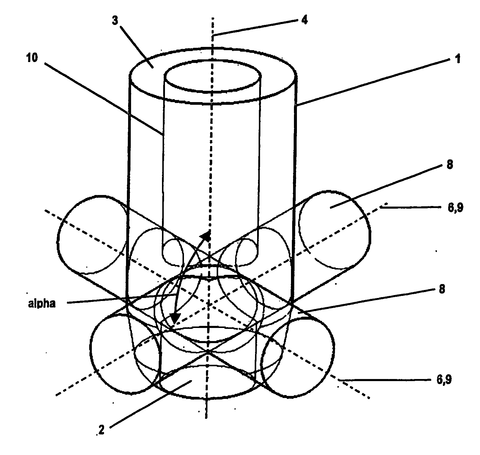
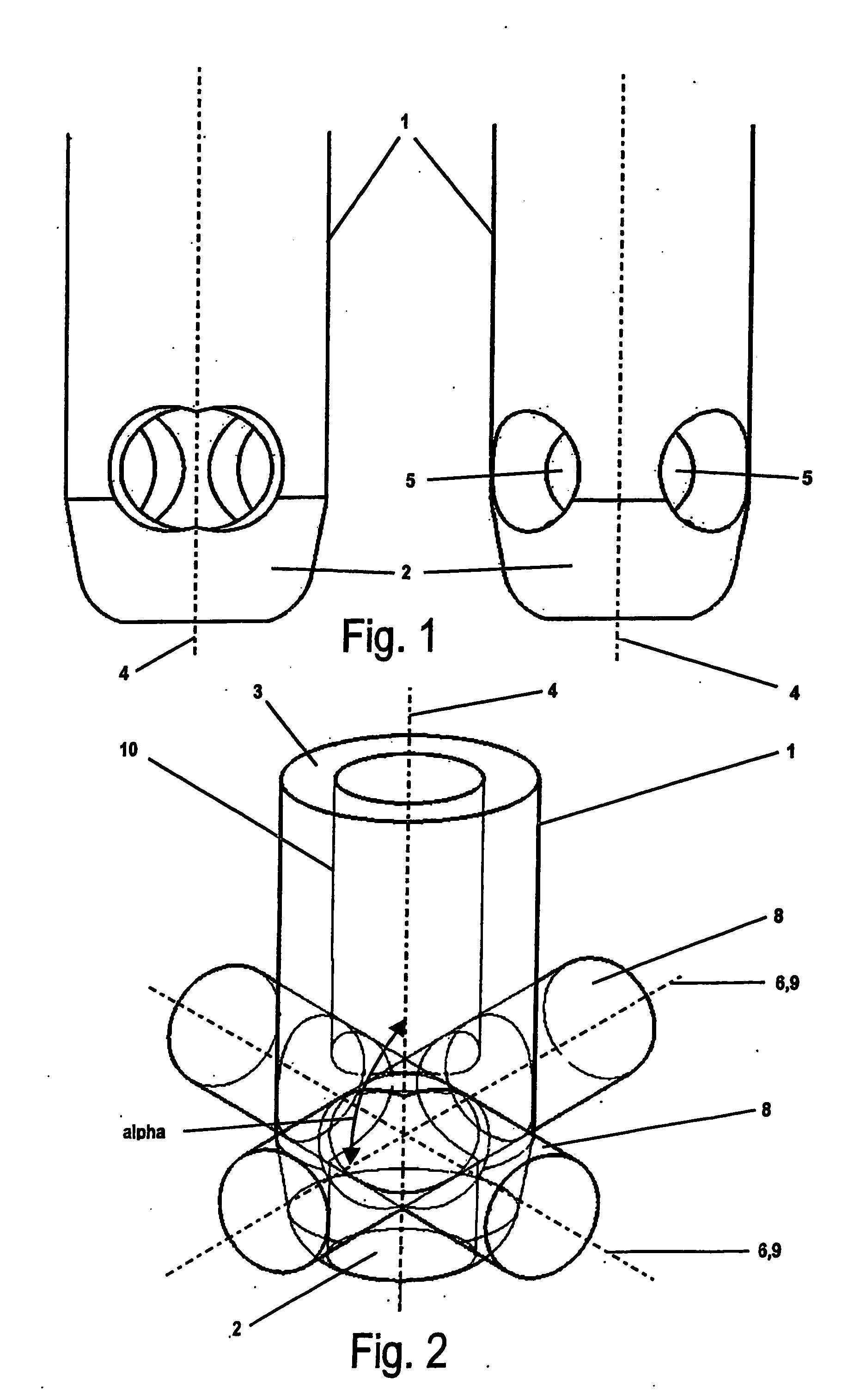
[0020] The intramedullary nail illustrated in FIGS. 1 to 3 is provided with a distal end 2 suitable for insertion in the medullary space of a tubular bone, a proximal end 3, a central longitudinal axis 4 and two cross holes 5 with a hole axis 6, each of which defines a virtual borehole cylinder 8 with a cylinder axis 9 corresponding to the hole axis 6 of the defining cross hole 5. The intramedullary nail has generally a constant diameter D and a longitudinal hole 10 coaxial to the central longitudinal axis 4.

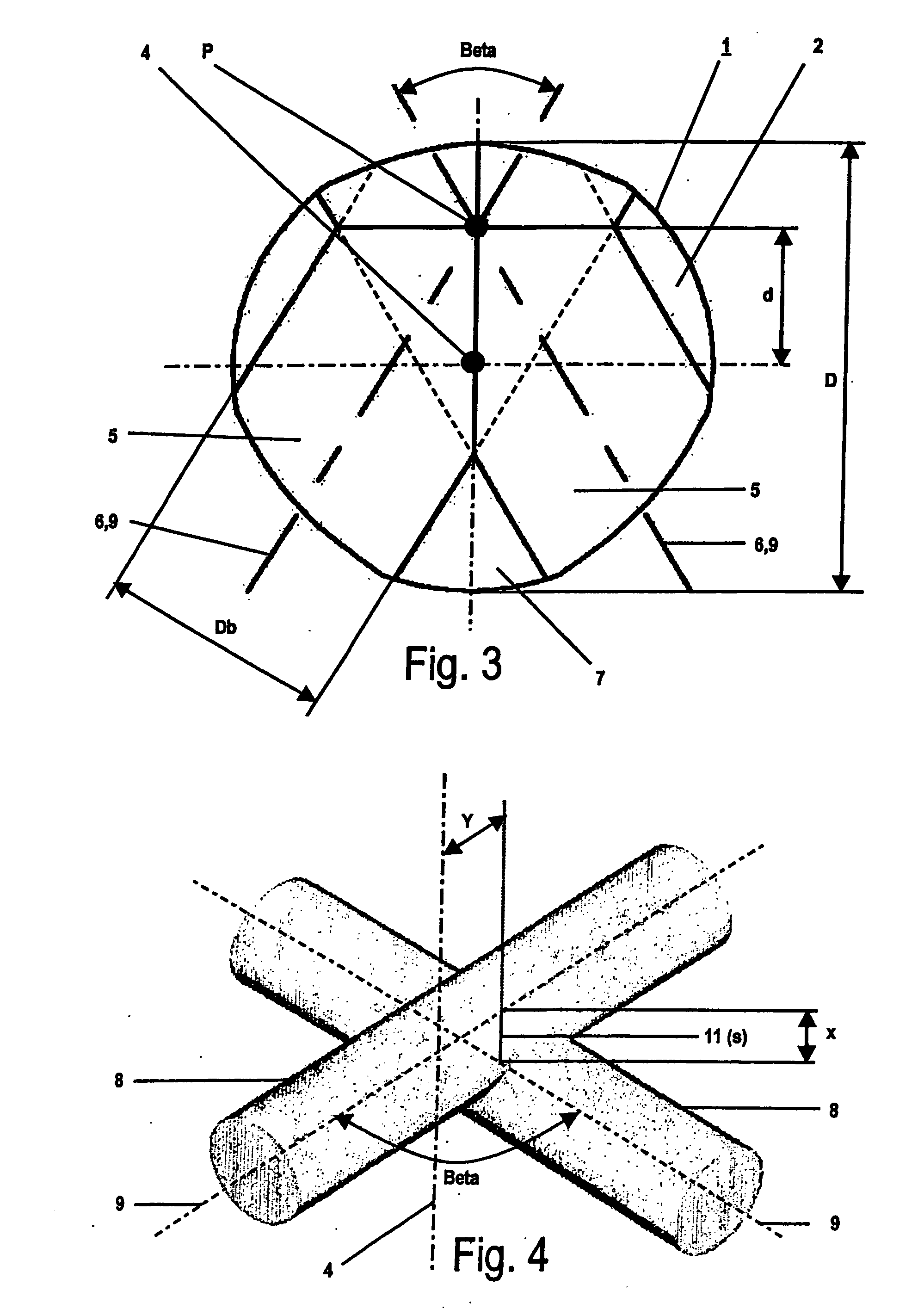
[0021] As illustrated in FIG. 3, the borehole cylinders 8 of the two cross holes 5 penetrate each other, wherein the cylinder axes 9 of the two mutually penetrating borehole cylinders 8 intersect at point P, which is at a distance d=0.4 D from the longitudinal axis 4. In other words, the point P does not lie on the longitudinal axis 4 of the intramedullary nail.

[0022] The mutually penetrating borehole cylinders 8 are provided with two separate entrance points in the intramedul...


PUM


Abstract

The intramedullary nail has a distal end suitable for insertion in the medullary space, wherein the segment of the intramedullary nail facing the distal end has a diameter D, a proximal end, a central longitudinal axis; and several cross holes with a hole axis, each of which defines a virtual borehole cylinder with a cylinder axis corresponding to the hole axis of the defining cross hole, wherein the borehole cylinders of at least two cross holes penetrate each other. The cylinder axes of the two mutually penetrating borehole cylinders do not have any common intersection point P on the longitudinal axis. This results in improved mechanical strength compared to the state of the art, without any need for the size of the cross section of the intramedullary nail to be increased.

Description

RELATED APPLICATION DATA [0001] The present application is a continuation of the U.S. National Stage designation of co-pending International Patent Application No. PCT / CH2003 / 000184, filed Mar. 21, 2003, the entire content of which is expressly incorporated herein by reference thereto.FIELD OF INVENTION [0002] The invention relates to an intramedullary nail for use in treating bone fractures, e.g., the distal tibia. More particularly, the present invention relates to an intramedullary nail having at least two intersecting transverse boreholes, wherein the axes of the two boreholes intersect at a point that is offset from the central longitudinal axis of the nail. BACKGROUND OF THE INVENTION [0003] The state of the art already includes intramedullary nails that have two intersecting transverse boreholes at the same height, so that the same intramedullary nail can be used both for a right and for a left tubular bone. [0004] The disadvantages of this prior known arrangement is that the...

Claims


Application Information

Patent Timeline
Patent Type & Authority Applications(United States)
IPC IPC(8): A61B17/56A61B17/68A61B17/72A61F2/28
CPCA61B17/72A61B17/7233A61B17/56A61B17/68A61F2/28
Inventor SCHLIENGER, ANDREBUETTLER, MARKUSSENN, PETER
Owner DEPUY SYNTHES PROD INC
Why Eureka
Try Eureka