Gun lock

a technology of gun lock and latch plate, which is applied in the direction of weapons, weapon components, safety arrangements, etc., can solve the problems of not providing an array of spring loaded pins, unauthorized use of guns, and time-consuming, so as to prevent surface scratching, prevent undesired movement of latch plate, and prevent surface scratching

Inactive Publication Date: 2006-06-01
SOPKO RILEY M
View PDF0 Cites 18 Cited by
  • Summary
  • Abstract
  • Description
  • Claims
  • Application Information

AI Technical Summary

Benefits of technology

[0008] This invention relates to a device for locking a gun, a gun lock, comprising a gun lock base having a top surface and a bottom surface, the top surface comprising a plurality of spring loaded pins covering the top surface of the gun lock base, the plurality of spring loaded pins automatically surrounding and immobilizing a gun or parts thereof placed on the top surface; a locking base; and, means for locking the gun or parts thereof between the gun lock base and the locking base. The plurality of spring loaded pins recess or release according to the pressure exerted by the object, herein a gun or parts thereof. The gun lock can include a locking post with locking teeth protruding from the gun lock base for engagement with an engagement tooth on the locking base when the device is in the lock position. The device can be locked or unlocked mechanically or electronically. The object such as the gun or parts thereof is sandwiched between the gun lock base and the locking base before locking the device. An example of a locking base suitable for pairing with the gun lock base comprises a latch plate having an engagement tooth for engagement with the locking teeth of the locking post. For a quick immobilization of the object, the plurality of pins on the top surface should be allowed to recess to or release from the top surface of the gun lock base according to the pressure exerted by the gun or parts thereof placed on top of the pins or on the top surface of the gun lock base. Each pin of the plurality of spring loaded pins are held by a channel of a plurality of channels or placed between interwoven strips of material on the gun lock base. Each spring loaded pin is kept inside the channel or between the interwoven strips of material on the gun lock base by an annular stopper on top of a spring enveloped portion of the pin and a plate placed over the annular stopper. A cover may be placed on the top of the plate to prevent surface scratching between the gun lock base and the gun or parts thereof. The cover has holes corresponding to each channel housing a spring loaded pin thereby allowing all the spring loaded pins to go through the cover. The cover is usually made of a rubber based material or soft flexible plastic material. It is recommended for the cover to have a smooth inner surface and a roughened outer surface. In this gun lock base and locking base pair that are locked mechanically, the latch plate has a cam boss and the key locking cylinder has a cam head. The cam boss and the cam head are made to abut each other when the device is locked. To prevent undesired movement of the latch plate, a cover plate may be placed on top of the latch plate. As in the gun lock base above, a pad may also be placed on top of the cover plate to prevent surface scratching between the locking base and the gun or parts thereof. The pad is similar to the cover of the gun lock base except that the pad does not have holes.

Problems solved by technology

Although adults usually lock the drawer or closet where the gun is stored, history has proven that this has not prevented unauthorized use of the gun.
This requires time since one or two pins are always not enough to prevent the trigger movement.
None of these inventions provide an array of spring loaded pins that would restrain a gun, a trigger and or a trigger head at whatever position it is laid between the opposing bodies.
Further, wear and tear between the tip of the pin and the surface of the locking plate may loosen and eventually allow some shifting between the locking plate and the housing.

Method used


Image

  • Gun lock
  • Gun lock
  • Gun lock

Examples


Embodiment Construction

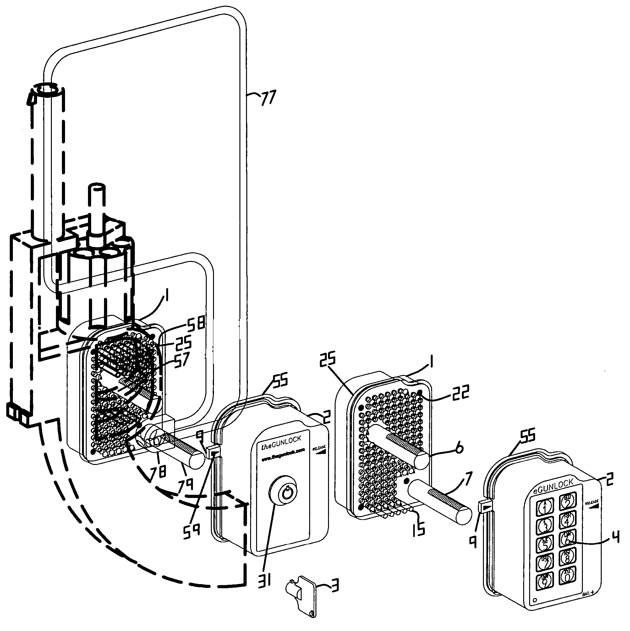
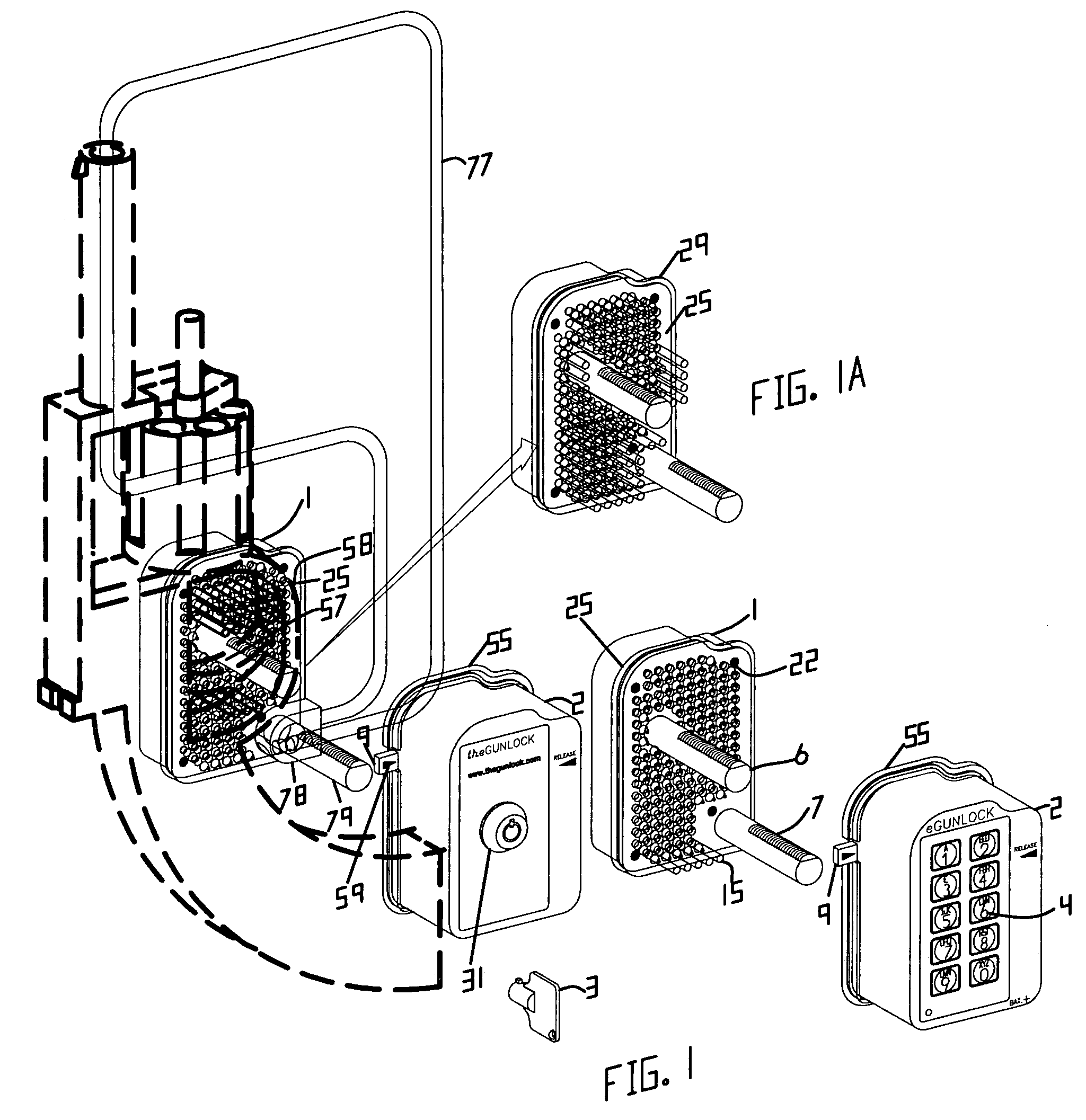
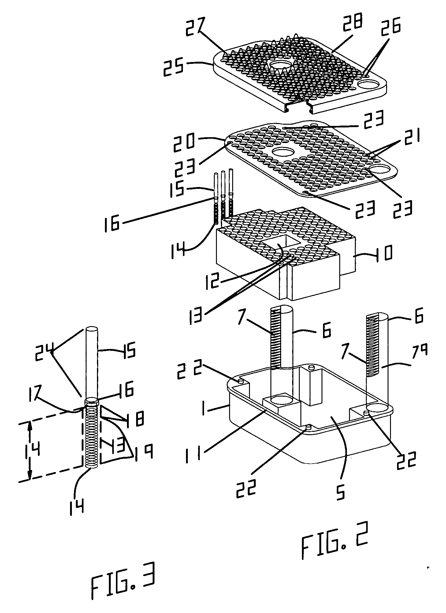
[0030] The detailed description represented-herein is not intended to represent the only way or the only embodiment in which the claimed invention may be practiced. The description herein is provided merely as an example or examples or illustrations of the claimed invention and should not be construed as the only way or as preferred or advantageous over other embodiments or means of practicing the invention. Any means of surrounding an object, herein a trigger and a trigger guard as examples, with a plurality of pins that automatically recess proportionately according to the pressure exerted by the object, usually its weight, is within the scope of this invention. In the example of the claimed gun lock herein, the restraining function of the plurality of pins automatically surrounding the trigger and / or the trigger guard on the gun lock base is coupled with a locking mechanism utilizing a latching plate with at least one engagement tooth for engaging with a corresponding locking tee...


PUM


Abstract

This invention relates to a gun lock, a device for locking a gun or parts thereof by securely situating the gun or parts thereof such as the trigger and the trigger guard between a gun lock base and a locking base. The gun lock base house a plurality of spring loaded pins for totally surrounding the gun or parts of the gun such as the trigger and/or the trigger guard when placed on top of the pins. The gun lock base pairs with a locking base housing a locking mechanism. The plurality of spring loaded pins covering the surface of a gun lock base immobilize the gun, trigger or trigger guard. The device can also be used to lock other objects in place aside from a gun or parts of the gun.

Description

BACKGROUND [0001] This invention relates to a gun lock, a device for locking a gun or parts thereof by securely situating the gun or parts thereof such as the trigger and the trigger guard between a gun lock base and a locking base. The gun lock base house a plurality of spring loaded pins, herein also simply referred to as pin, for totally surrounding the gun or parts of the gun such as the trigger and / or the trigger guard when placed on top of the pins. The gun lock base in the example herein pairs with a locking base housing a latch plate for locking the gun lock when an engagement tooth on the latch plate engages with the locking teeth on the locking posts situated on the gun lock base. The plurality of spring loaded pins covering the surface of a gun lock base to immobilize the gun, trigger or trigger guard is an aspect of this invention that can be implemented with other locking bases to improve their performance. The claimed device can also be used to lock other objects in pl...

Claims


Application Information

Patent Timeline
Patent Type & Authority Applications(United States)
IPC IPC(8): F41A17/46
CPCF41A17/54
Inventor SOPKO, RILEY M.
Owner SOPKO RILEY M
Why Eureka
Try Eureka