Tube bender
- Summary
- Abstract
- Description
- Claims
- Application Information
AI Technical Summary
Benefits of technology
Problems solved by technology
Method used
Image
Examples
Embodiment Construction
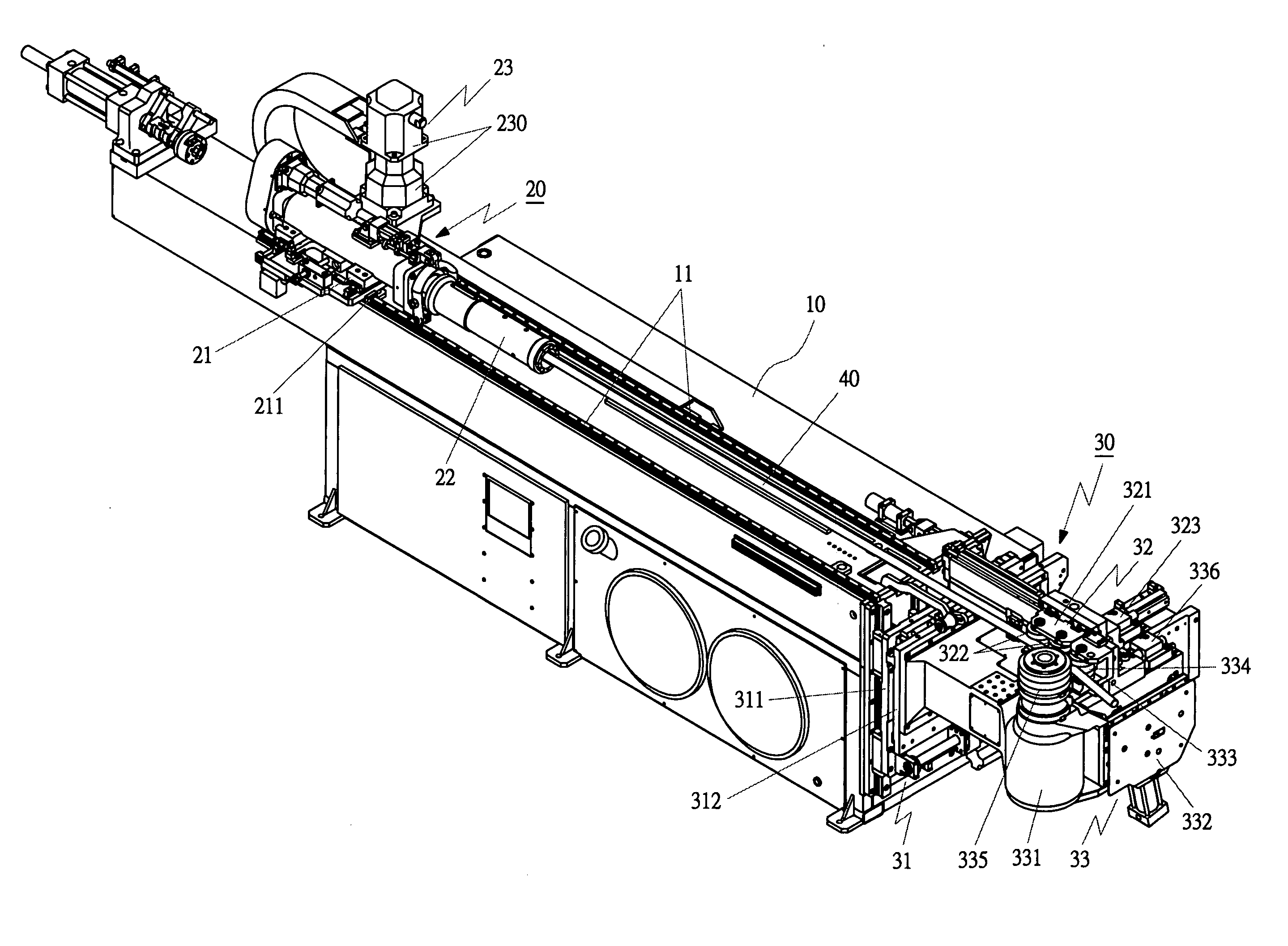
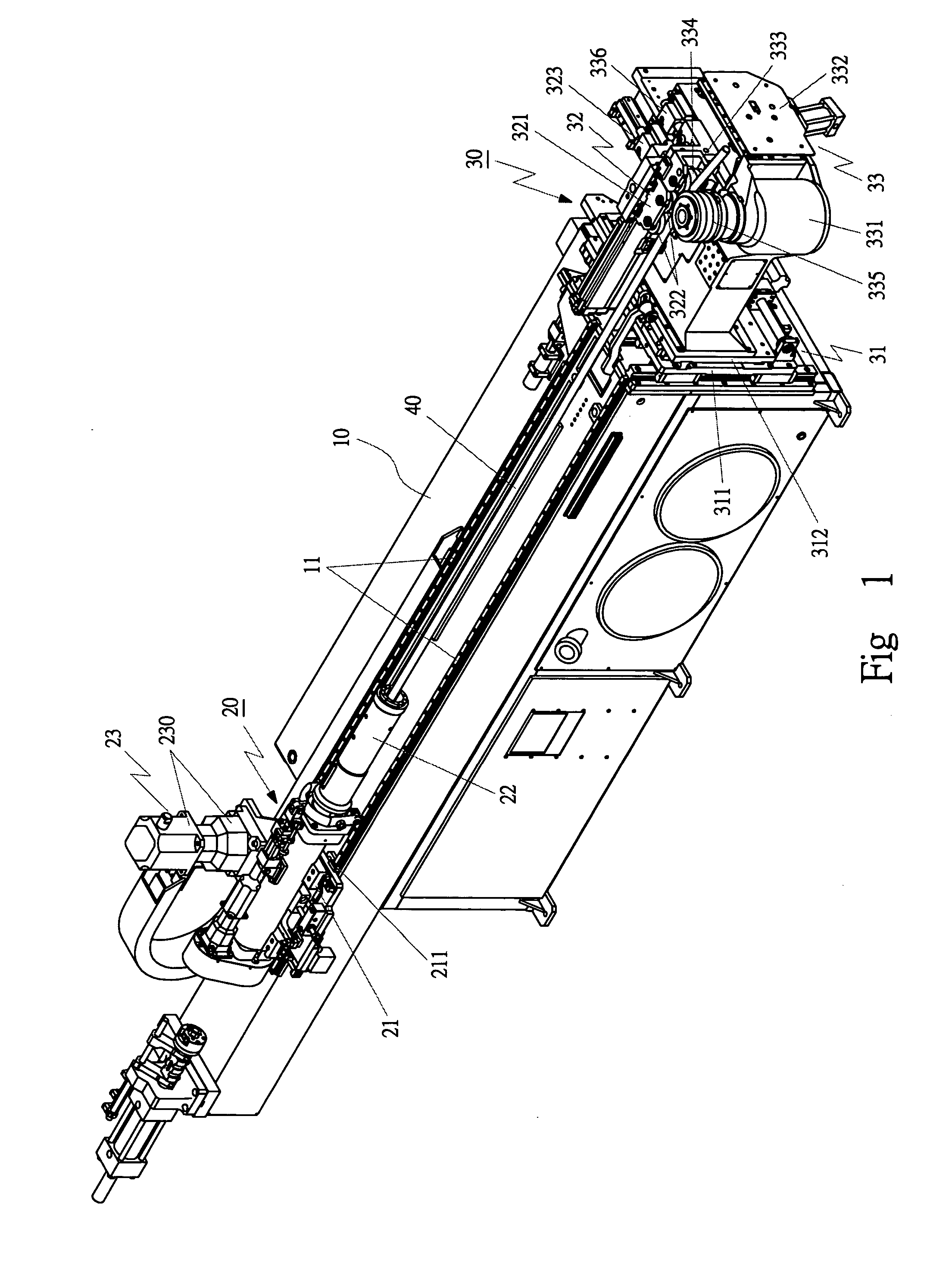
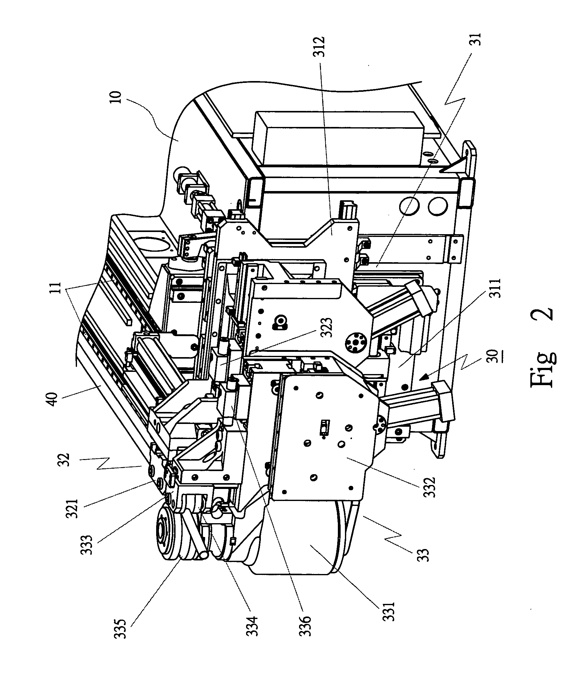
[0023] A first embodiment of a tube bender in the present invention, as shown in FIGS. 1, 2 and 3, includes a worktable 10, a tube-pushing device 20, and a tube-bending device 30 as main components combined together.
[0024] The worktable 10 has a number-style controlling device (not shown) belonging to a CNC number-style controlling system, and a rail 111 fixed on the worktable 10.
[0025] The tube pushing device 20 is positioned on the worktable 10, consisting of a moving base 21, a clamper 22, and a driver 23. The moving base 21 has a rail groove 211 symmetrically provided at two sides and connected with the rail 11 in a dovetail condition to let the moving base 21 to move smoothly on the rail 11. The clamper 22 is located at one side of the moving base 21, controlled by the controlling device for clamping and loosening a tube 40 being bent. The pushing driver 23 is connected with the moving base 21, consisting of a motor and a gear case 230, and using oil pressure or a threaded ro...
PUM
 Abstract
Description
Claims
Application Information
 - R&D
- Intellectual Property
- Life Sciences
- Materials
- Tech Scout
- Unparalleled Data Quality
- Higher Quality Content
- 60% Fewer Hallucinations
Browse by: Latest US Patents, China's latest patents, Technical Efficacy Thesaurus, Application Domain, Technology Topic, Popular Technical Reports.
© 2025 PatSnap. All rights reserved.Legal|Privacy policy|Modern Slavery Act Transparency Statement|Sitemap|About US| Contact US: help@patsnap.com


