Compact structure of spark plug designed to ensure desired heat range

a compact structure and spark plug technology, applied in spark plugs, machines/engines, mechanical equipment, etc., can solve the problems of reducing the thermal conductivity the lack of thermal energy transfer from the outer surface the spark plug, so as to minimize the thermal expansion of the center electrode, reduce the size of the spark gap, and minimize the effect of the center electrod

Active Publication Date: 2006-06-01
DENSO CORP
View PDF1 Cites 16 Cited by
  • Summary
  • Abstract
  • Description
  • Claims
  • Application Information

AI Technical Summary

Benefits of technology

[0011] It is another object of the invention to provide a compact structure of a spark plug for internal combustion engines which is designed to ensure a desired heat range.
[0018] The thermal conductive metal-made portion of the center electrode has a top end located 2 mm to 7 mm away from the tip end of the porcelain insulator. This ensures a desired heat range of the spark plug and a physical strength of the tip of the porcelain insulator.

Problems solved by technology

The whole of the Cu-made core 91 is, however, disposed inside the Ni-made outer layer 92, thus resulting in a lack in transferring thermal energy from the outer surface of the center electrode to a porcelain insulator surrounding the center electrode in terms of improvement of the heat range of the spark plug.
Such decreasing results in a reduction in thermal conductivity of the center electrode, which leads to a decrease in the heat range of the spark plug.
This, however, encounters the drawback in that the antifouling ability of the spark plug degrades.

Method used


Image

  • Compact structure of spark plug designed to ensure desired heat range
  • Compact structure of spark plug designed to ensure desired heat range
  • Compact structure of spark plug designed to ensure desired heat range

Examples


first embodiment

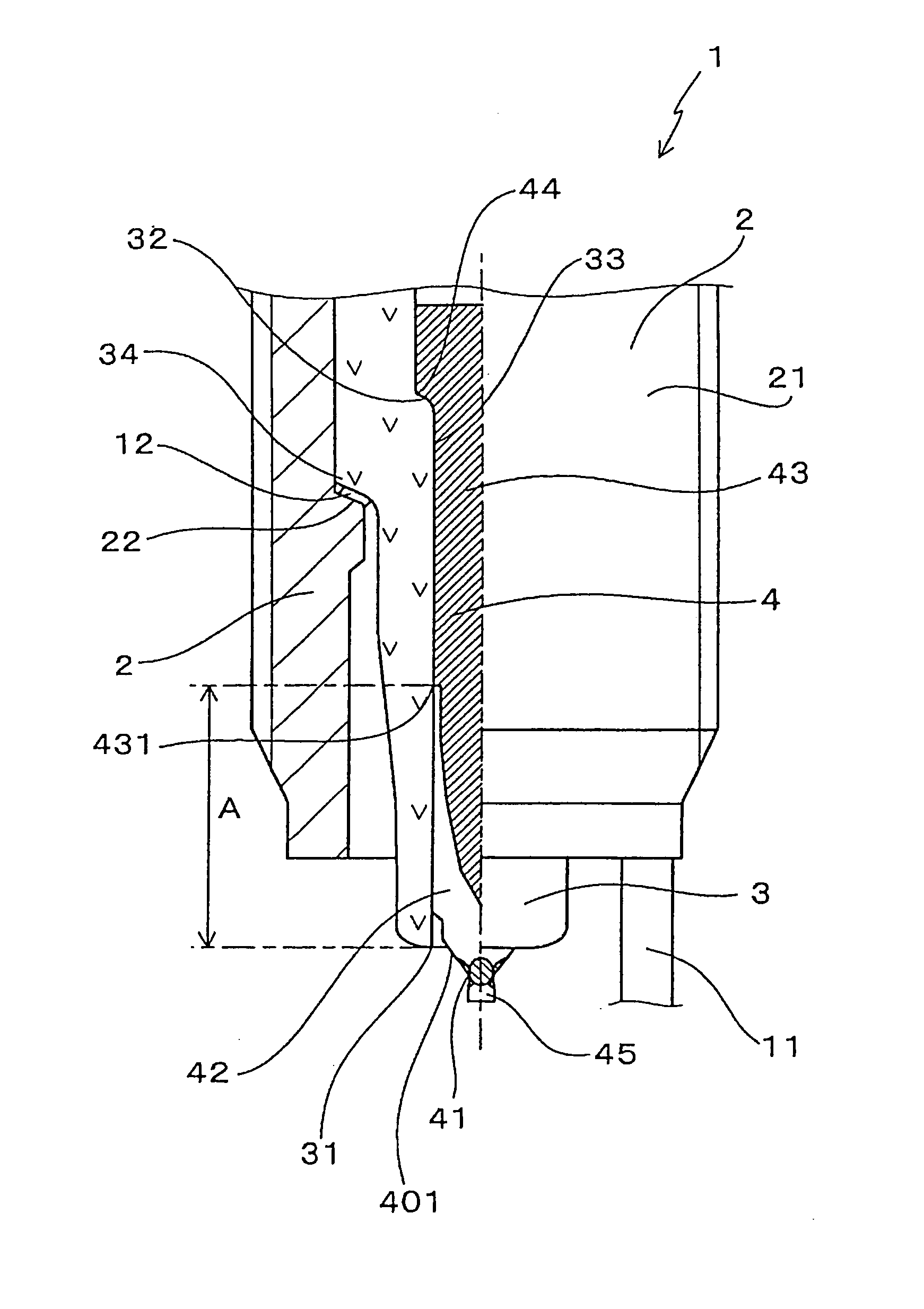
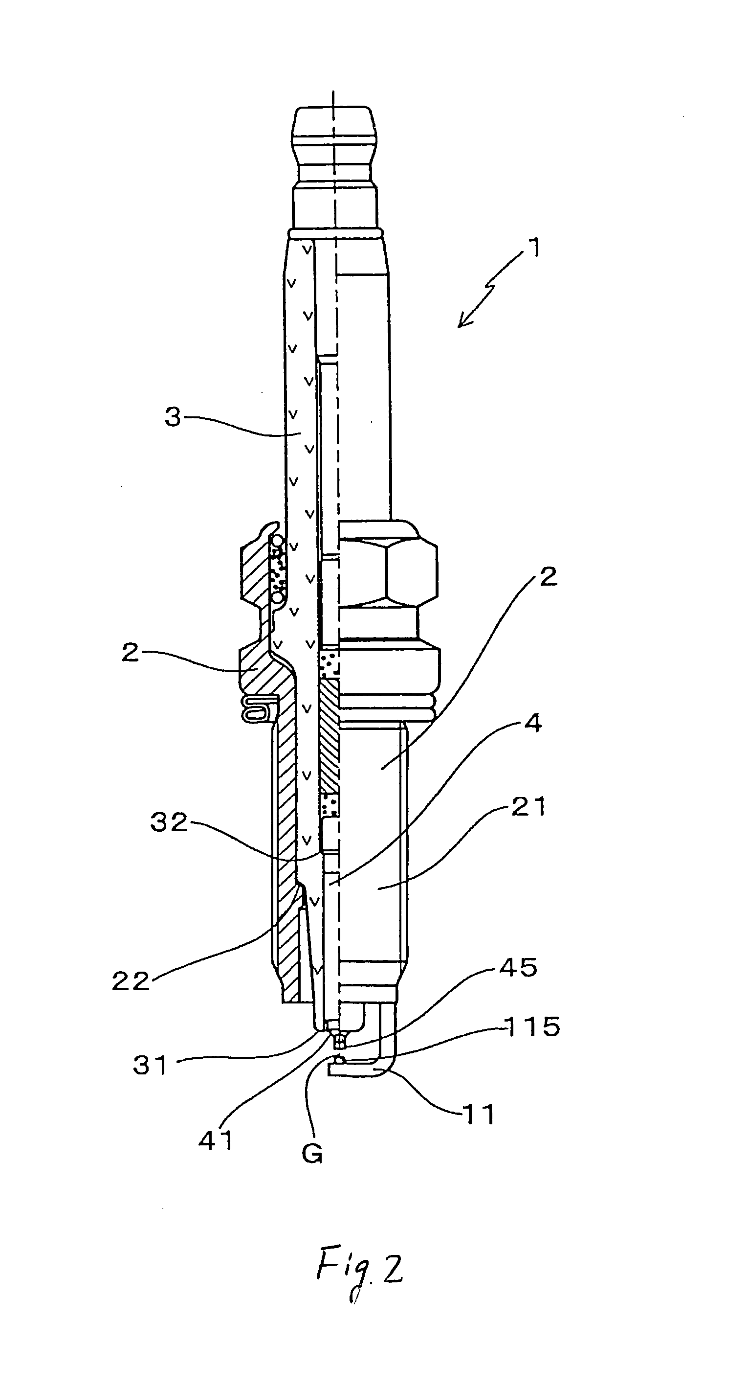
[0030] Referring now to the drawings, particularly to FIGS. 1 and 2, there is shown a spark plug 1 according to the invention which may be employed in internal combustion engines.

[0031] The spark plug 1 includes a hollow cylindrical metallic plug-mounting shell 2, a porcelain insulator 3, a center electrode 4, and a ground electrode 11.

[0032] The plug-mounting shell 2 has formed on an outer periphery thereof a plug-installation thread 21 for installing the spark plug 1 in the engine. The thread 21 has a thread diameter of M12 (i.e., 12 mm) or less, as specified in JIS. The thread diameter is preferably greater than or equal to M8. The porcelain insulator 3 is retained inside the plug-mounting shell 2 to have a tip end 31 protruding from an end of the plug-mounting shell 2. The center electrode 4 is retained in the porcelain insulator 3 and has a tip 41 exposed outside the tip end 31 of the porcelain insulator 3. The ground electrode 11 is welded at a base end thereof to the plug-mo...

second embodiment

[0050]FIG. 4 shows the spark plug 1 according to the invention in which the porcelain insulator 3 has an annular shoulder seat 320 located closer to the top thereof than the shoulder seat 22 of the plug-mounting shell 2.

[0051] The center electrode 4, like the first embodiment, consists of the high thermal conductive metal-made portion 43 and the oxidation resistant alloy-made portion 42. The high thermal conductive metal-made portion 43 has a top end 432 located 2 mm to 7 mm away from the tip end 31 of the porcelain insulator 3. Specifically, the axial distance B between the top end 432 of the high thermal conductive metal-made portion 43 and the tip end 31 of the porcelain insulator 3 lies within a range of 2 mm to 7 mm.

[0052] The annular shoulder seat 320 serving to bear the center electrode 4 is formed on the inner wall of the porcelain insulator 3 and protrudes inside the axial bore 33 of the porcelain insulator 3. The center electrode 4 has the annular shoulder 44 formed on th...

third embodiment

[0055]FIG. 5 shows the spark plug 1 according to the invention in which the high thermal conductive metal-made portion 43 of the center electrode 4 is made from a composite material containing a combination of Cu and Ni.

[0056] The high thermal conductive metal-made portion 43 consists essentially of an outer peripheral portion 433 and a core portion 434 extending inside the outer peripheral portion 433. The outer peripheral portion 433 is made from pure Cu that has a higher thermal conductivity. The core portion 434 is made from pure Ni that has a lower coefficient of thermal expansion. The outer peripheral portion 433 surrounds the whole of the core portion 434 and has a thickness of 0.1 mm to 0.4 mm.

[0057] The high thermal conductive metal-made portion 43 is made of a combination of Cu having a higher thermal conductivity and Ni having a lower coefficient of thermal expansion, thus minimizing a defect of the center electrode 4 caused by the thermal expansion thereof and also esta...


PUM


Abstract

A spark plug for an internal combustion engine is provided which has a center electrode made up of an oxidation resistant alloy-made portion and a thermal conductive metal-made portion. The oxidation resistant alloy-made portion occupies at least a top portion of the center electrode exposed outside a porcelain insulator. The thermal conductive metal-made portion is exposed to a portion of an outer periphery of the center electrode which faces a insulator mount portion of a spark-mounting shell through the porcelain insulator in a direction perpendicular to an axial direction of the center electrode, thereby facilitating transfer or dispersal of heat from the center electrode to the mounting shell through the porcelain insulator to ensure a desired heat range.

Description

CROSS REFERENCE TO RELATED DOCUMENT [0001] The present application claims the benefit of Japanese Patent Application No. 2004-344506 filed on Nov. 29, 2004, the disclosure of which is incorporated herein by reference. BACKGROUND OF THE INVENTION [0002] 1. Technical Field of the Invention [0003] The present invention relates generally to a compact structure of a spark plug for internal combustion engines which may be employed in automotive vehicles, cogeneration systems, or gas feed pumps, and more particularly to such a spark plug designed to ensure a desired heat range. [0004] 2. Background Art [0005] Spark plugs are usually used in internal combustion engines such as ones mounted in automotive vehicles. The output of the engine is increased or the fuel consumption rate is improved by increasing the diameter of intake valves or exhaust valves leading to an intake manifold or an exhaust manifold of the engine. The cooling system is also improved by increasing the size of a water jac...

Claims


Application Information

Patent Timeline
Patent Type & Authority Applications(United States)
IPC IPC(8): H01T13/20
CPCH01T13/20H01T13/39
Inventor KANAO, KEIJI
Owner DENSO CORP
Why Eureka
Try Eureka