Passive magnetic latch

a magnetic latch and passive technology, applied in the field of magnetic latches, can solve the problems of insufficient beam closure without an external field, and the practicality of magnetic latches in many applications

Active Publication Date: 2006-06-01
TELEDYNE BROWN ENG A DIV OF TELEDYNE
View PDF16 Cites 19 Cited by
  • Summary
  • Abstract
  • Description
  • Claims
  • Application Information

AI Technical Summary

Benefits of technology

[0005] In one general aspect, embodiments of the present invention are directed to a passive magnetic latch. The latch includes a magnetically-actuated switch and a hard, non-linear biasing magnet. The magnetically-actuated switch includes components that, when polarized, cause the magnetically-actuated switch to transition from a first state (such as open) to a second state (such as closed). According to various embodiments, the magnetically-actuated switch may be a reed switch with at least two soft magnetic beams that, when polarized, transition from the first state to the second state. The biasing magnet is positioned proximate to the reed switch such that when the magnetization of the biasing magnet is changed by an external effect to thereby induce a modified magnetic field from the biasing magnet, the modified magnetic field polarizes the beams of the reed switch such that the reed switch transitions from the first state to the second state and the reed switch remains in the second state after the external effect is removed. A second external effect may be used to change the magnetization of the biasing magnet causing de-polarization of the beams of the reed switch such that the switch transitions from the second state back to the first state and remains in the first state after the second external effect is removed. In this way, the passive magnetic latch may operate as a remote ON / OFF switch that is responsive to the external effects, which do not need to physically contact the biasing magnet, but merely need to suitably alter the magnetization of the biasing magnet.

Problems solved by technology

Such latching devices also typically include secondary solenoids which provide a field sufficient to retain the beams of the reed switch in the closed position, but insufficient to close the beams without an external field.
Because the solenoids, however, require non-zero electrical current (or power), in circumstances when no such current can be provided, or it proves to be an excessive drain on a power supply, such magnetic latches are not practical for many applications.

Method used


Image

  • Passive magnetic latch
  • Passive magnetic latch
  • Passive magnetic latch

Examples


Embodiment Construction

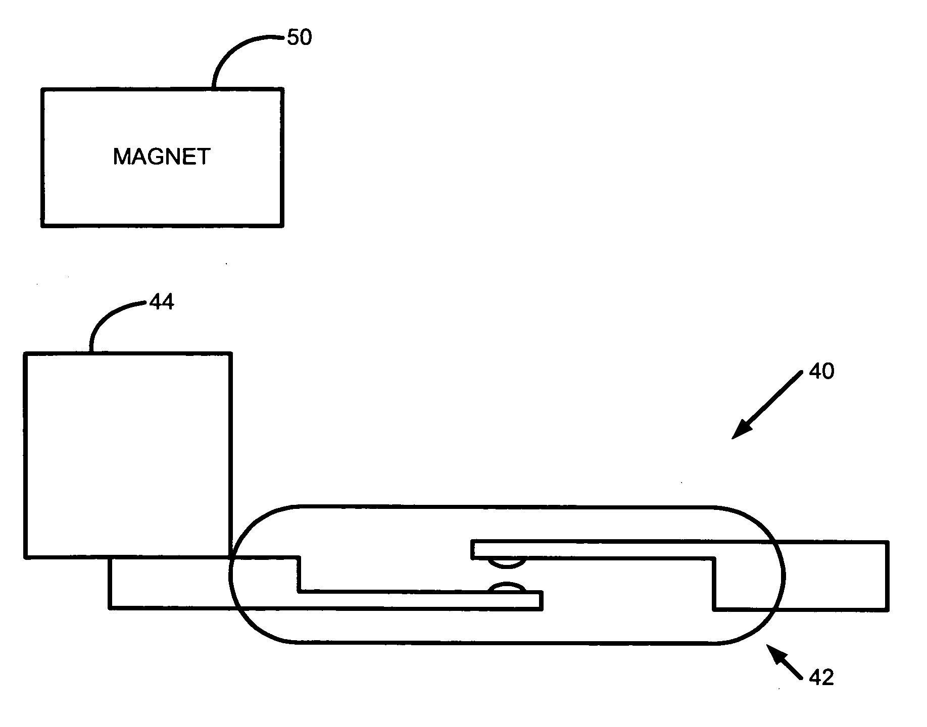
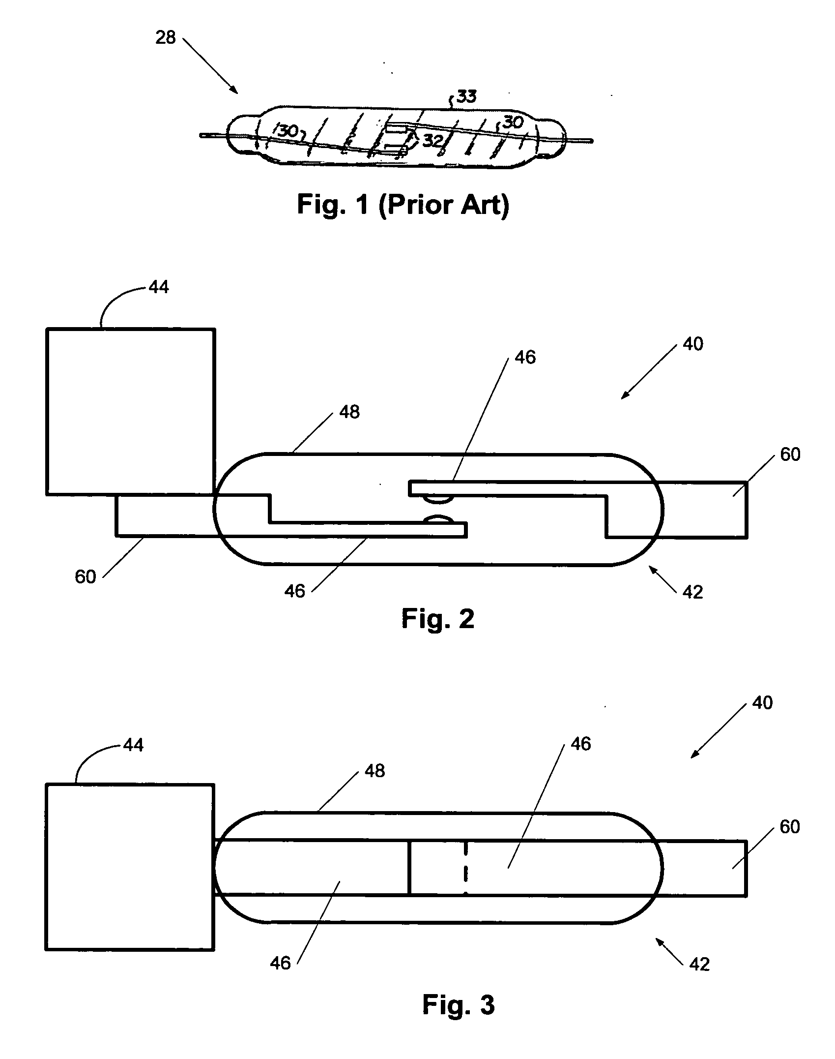
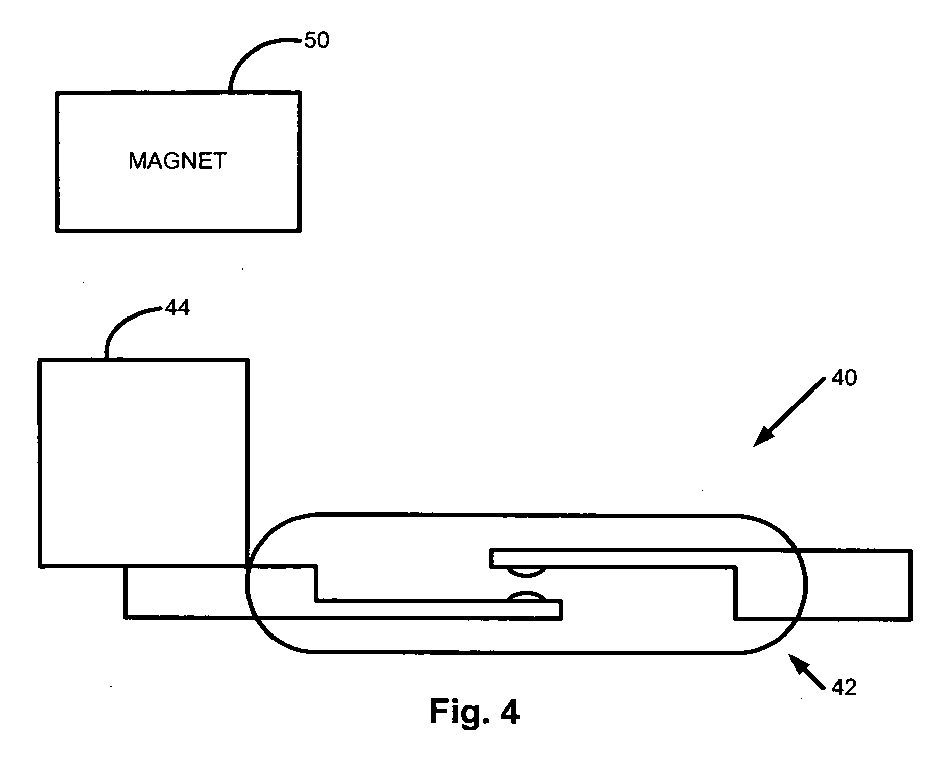
[0014]FIG. 2 is a side-view and FIG. 3 is a top-view of a passive magnetic latching device (or latch) 40 according to various embodiments of the present invention. As shown in these figures, the latching device 40 may include a magnetically-actuated switch 42 and a biasing magnet 44. The magnetically-actuated switch 42 may include components which, when polarized, cause the switch 42 to transition from a first state (such as open) to a second state (such as closed). According to various embodiments, the magnetically-actuated switch 42 may be, for example, a reed switch. The reed switch, as shown in FIGS. 2 and 3, may include a number of beams 46 made of a soft magnetic material, such as nickel, nickel-iron or nickel iron molybdenum based alloys, soft ferrites such as nickel-zinc or manganese-zinc ferrites, or combinations of these materials. The beams 46 may be configured such that there is a small gap between the contacts of the beams 46 in the absence of a polarizing magnetic fiel...


PUM


Abstract

A passive magnetic latch is disclosed. The latch includes, according to various embodiments, a magnetically-actuated switch and a hard, non-linear biasing magnet. The switch may include components that, when polarized, cause the switch to transition from a first state to a second state. The biasing magnet is positioned proximate to the switch such that when the magnetization of the biasing magnet is changed by an external effect to thereby induce a modified magnetic field from the biasing magnet, the modified magnetic field polarizes the components of the switch such that the switch transitions from the first state to the second state and remains in the second state after the external effect is removed. A second external effect may be used to again change the magnetization of the biasing magnet such that the components of the switch depolarize and the switch transitions back the first state. As such, the magnetic latch may act like a remote ON/OFF switch.

Description

BACKGROUND [0001] The present invention generally concerns latching devices (i.e., latches) and, more particularly, magnetic latches. [0002] The most common element designed to provide ON / OFF switching action when activated magnetically is a reed switch. As shown in FIG. 1, a normally-open reed switch 28 generally consists of two beams 30 disposed in a hermetically sealed glass cover 33. The beams 30 are made of magnetically permeable (i.e., soft) metal placed in close proximity to each other with a small gap between the ends (or contacts) 32 of the beams 30. When magnetic field of proper configuration is applied to the device, the beams 30 polarize magnetically such that they attract and form a mechanical and electrical contact. When the field is removed, the beams return to the initial state such that there is no electrical contact between the beams. [0003] In order to polarize the beams in magnetically opposite states (to cause attraction between the beams), the field around the ...

Claims


Application Information

Patent Timeline
Patent Type & Authority Applications(United States)
IPC IPC(8): H01H1/66
CPCH01H36/0026H01H36/0073
Inventor GRIGOROV, ILYA L.
Owner TELEDYNE BROWN ENG A DIV OF TELEDYNE
Why Eureka
Try Eureka