
Systems and methods for reducing process direction registration errors of a printhead using a linear array sensor

a technology of process direction and linear array, which is applied in the field of system and method for reducing process direction registration errors of printheads, can solve the problems of skewing of the image produced by the printhead, roll and y-axis stitch, and print defects at the boundary between two printheads, so as to achieve high frequency banding and reduce process direction registration errors

Inactive Publication Date: 2006-06-01
XEROX CORP
View PDF2 Cites 31 Cited by
  • Summary
  • Abstract
  • Description
  • Claims
  • Application Information

AI Technical Summary

Benefits of technology

[0010] Various exemplary embodiments according to the present invention provide systems and methods for reducing process direction registration errors using test patterns. In various exemplary embodiments, a method for detecting process direction registration errors comprises obtaining a first dash minimum response curve, the first dash minimum response curve outlining a first plurality of minimal responses sensed from a first plurality of dashes in a test pattern, the dashes in the test pattern including being spaced substantially equally in a cross process direction, each dash extending substantially the same length in a process direction, the process direction perpendicular to the cross process direction, at least one dash having a position shift in the process direction from a neighboring dash; obtaining a second dash minimum response curve, the second dash minimum response curve outlining a second plurality of minimal responses sensed from a second plurality of dashes in the test pattern; and determining a difference in phase and / or frequency between the first and second sinusoidal curves.

Problems solved by technology

When a printer uses a plurality of printheads to write to a drum rotating underneath them, print defects can occur at the boundary between two printheads, if the two printheads are not precisely aligned.
These print defects include roll and y-axis stitch.
Roll causes a skew of the image produced by the printhead relative to the print medium, such as paper.
If an image was printed entirely with a single printhead, small amounts of roll would not be perceivable.
Such a translation causes an objectionable streak.
When a printhead uses multiple passes to produce high resolution images, another print defect, the y-axis interlace, may occur.
The pass-to-pass errors can also introduce high frequency banding in a halftone image.

Method used


Image

  • Systems and methods for reducing process direction registration errors of a printhead using a linear array sensor
  • Systems and methods for reducing process direction registration errors of a printhead using a linear array sensor
  • Systems and methods for reducing process direction registration errors of a printhead using a linear array sensor

Examples


Embodiment Construction

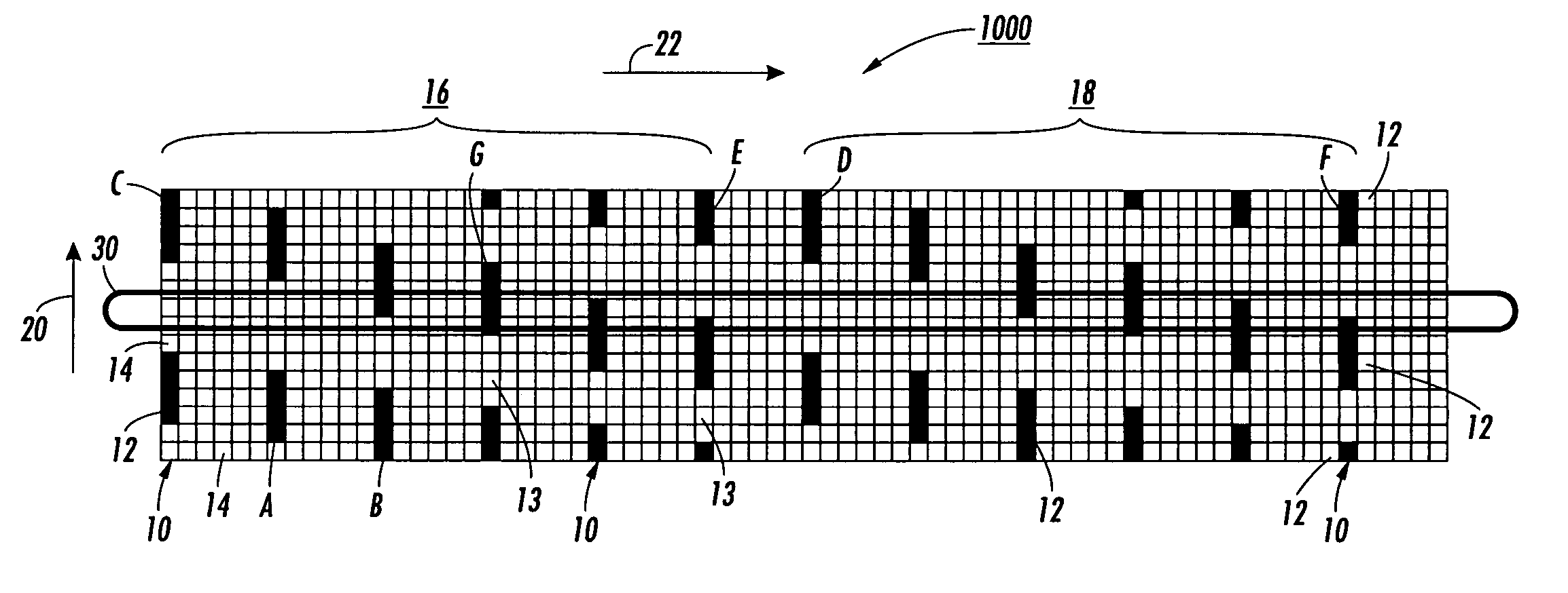
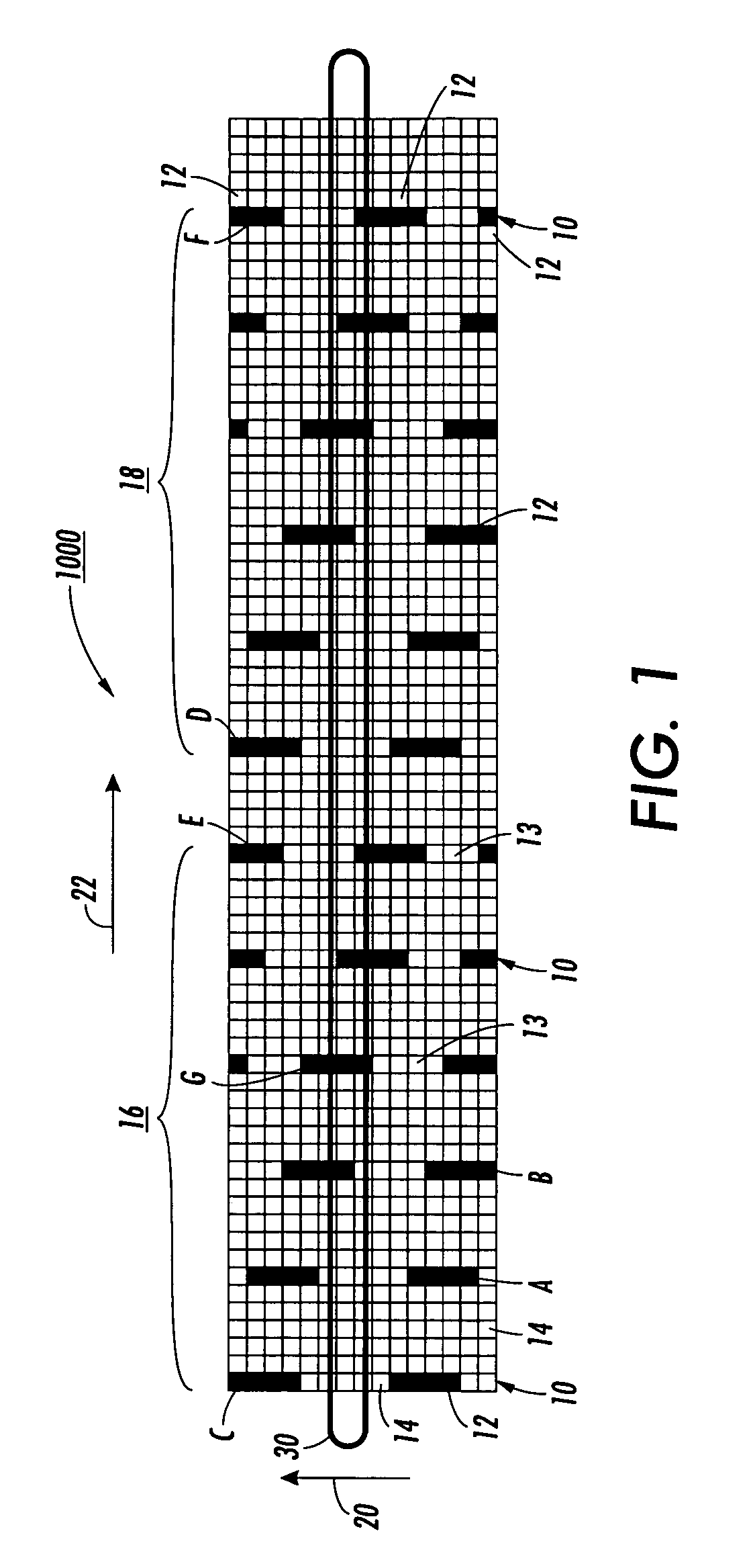
[0022]FIG. 1 illustrates an exemplary embodiment of a test pattern 1000 according to this invention. As shown in FIG. 1, the test pattern 1000 may include a plurality of dashed lines 10. Each dashed line 10 extends in the process direction 20 (the vertical direction or y-axis direction). The plurality of dashed lines 10 are substantially equally spaced or separated from each other in the cross process direction 22 (horizontal direction, or x-axis direction).

[0023] As shown in FIG. 1, each dashed line 10 includes a plurality of dashes 12 running in the process direction 20. The dashes 12 of a dashed line 10 are substantially equally spaced or separated from each other in the process direction 20.

[0024] As shown in FIG. 1, a dash 12 in a dashed line 20 is shifted for a certain number of pixels 14 in the process direction 20 relative to a dash 12 of a neighboring dashed line 10. For example, as shown in FIG. 1, dash A is ahead of dash B in the process direction 20. The shift may be a...


PUM


Abstract

Systems and methods are provided for detecting process direction registration errors in a printer. The errors are detected by analyzing a metric of a dash minimum response obtained from a test pattern. The test pattern contains dashes. At least one dash is shifted in the process direction in relation to another dash.

Description

BACKGROUND OF THE INVENTION [0001] 1. Field of Invention [0002] This invention relates to systems and methods for reducing process direction registration errors of a printhead using a linear array sensor. [0003] 2. Description of Related Art [0004] Fast printing with a direct marking engine requires the use of multiple printheads. For example, four aligned printheads may be used in a printer to write to a drum rotating underneath them. Each printhead has six degrees of positional freedom, three translational and three rotational. The printheads need be precisely aligned so that there is a smooth transition from one printhead to the other in the printed image. [0005] In order to achieve a high resolution, it may also be necessary for the drum of the printer to make multiple passes while the printheads are translated after each rotation along the axis of the drum. In this case, the transition of the printhead needs to be precise, to achieve equal spacing between the centers of the pri...

Claims


Application Information

Patent Timeline
Patent Type & Authority Applications(United States)
IPC IPC(8): B41J29/393
CPCB41J2/155
Inventor MIZES, HOWARD A.PAUL, PETERWALLACE, STANLEY J.BORTON, MICHAEL D.OSSMAN, KENNETH R.
Owner XEROX CORP
Learn More