Linear frequency modulation continuous wave radar transceiving front end

A technology of linear frequency modulation and wave radar, which is applied in the direction of radio wave measurement systems and instruments, can solve the problems of not too much transmission power, difficulty in measuring multiple targets, and short measurement distance, so as to reduce manufacturing costs, reduce device costs, The effect of simple structure

Inactive Publication Date: 2018-08-28
10TH RES INST OF CETC
View PDF4 Cites 17 Cited by
  • Summary
  • Abstract
  • Description
  • Claims
  • Application Information

AI Technical Summary

Problems solved by technology

When the same antenna is used for sending and receiving signals, the leakage of the transmitter power will block the receiver, and the transmission power should not be too large, which makes the measurement distance shorter and it is difficult to measure multiple targets at the same time. If you want to measure multiple targets at the same time , it is necessary to use a large number of filters, making the device too complicated and inconvenient to use

Method used


Image

  • Linear frequency modulation continuous wave radar transceiving front end
  • Linear frequency modulation continuous wave radar transceiving front end
  • Linear frequency modulation continuous wave radar transceiving front end

Examples


Embodiment Construction

[0017] The integrated integrated LFM continuous wave radar transceiver front end proposed by the present invention will be described in detail below in conjunction with the accompanying drawings and specific implementation steps.

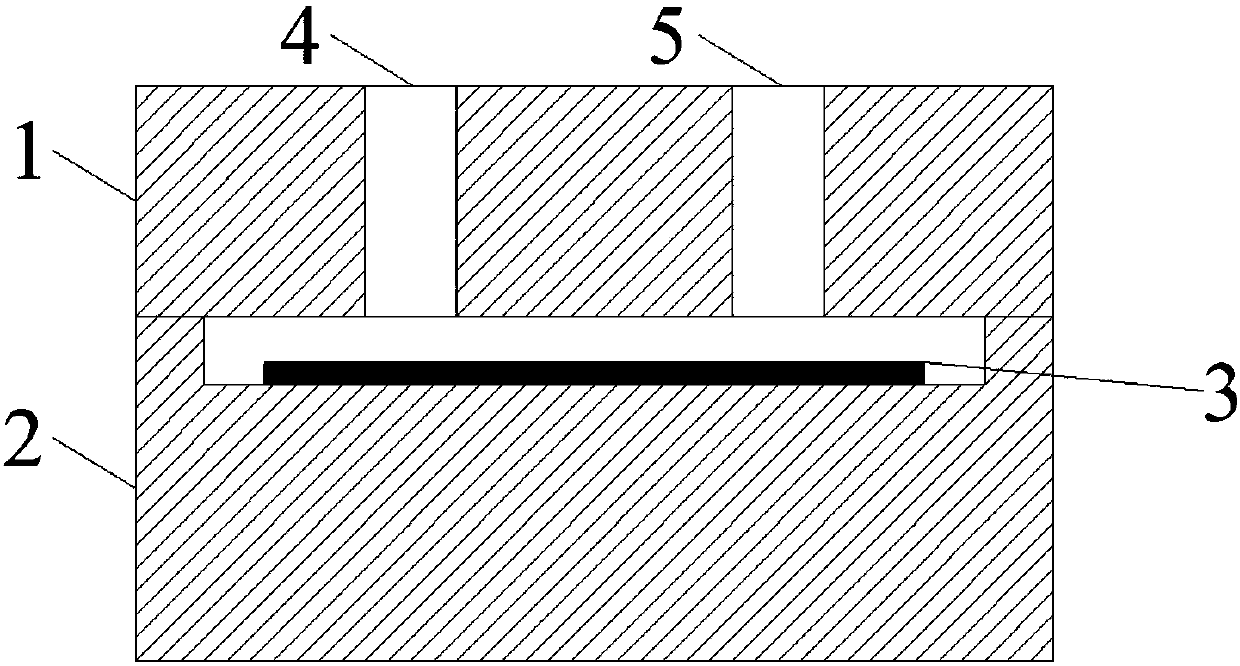
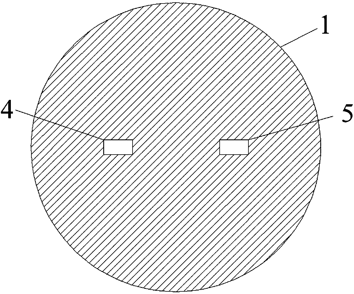
[0018] refer to Figure 1-Figure 3 . A linear frequency modulation continuous wave radar transceiver front-end, comprising: a transceiver front-end composed of two parts, an upper cavity 1 and a lower cavity 2, and a radio frequency radio frequency fixed between the upper cavity 1 and the lower cavity 2 by screws The circuit 3 , the waveform generating circuit 13 and the intermediate frequency signal processor 14 connected to the radio frequency circuit 3 . The upper cavity 1 and the lower cavity 2 are made of metal materials, and the upper cavity has a transmitting channel and a receiving channel with a symmetrical central axis. The transmitting antenna 4 and the receiving antenna 5 are respectively integrated in the transmitting channel and the r...


PUM


Abstract

The invention discloses a linear frequency modulation continuous wave radar transceiving front end, and aims to provide a transceiving front end which is simple in structure, high in integration, small in size, and easy to realize integration in one step. According to the technical scheme, a transmitting antenna (4) and a receiving antenna (5) are integrated in the cylinder transmitting channel and the receiving channel of an upper cavity (1), wherein the transmitting channel and the receiving channel are symmetrical to the central axis, a radio frequency circuit (3) is installed in a disc cavity formed in the lower cavity cylinder, the radio frequency circuit (3) is used for carrying out the energy transmission with the transmitting antenna and the receiving antenna by means of electromagnetic coupling through the transmitting antenna and the receiving antenna, a waveform generator is used for inputting the generated modulation signal v (t) into a voltage-controlled oscillator in theradio frequency circuit 3, the voltage-controlled oscillator is used for modulating the modulation signal to a microwave frequency band, the generated frequency modulation signal is amplified throughmultiple times of frequency doubling and is used as a transmitting signal of the transmitting antenna to be transmitted out.

Description

Background technique [0001] With the continuous development of digital technology and signal processing technology, the FMCW radar using linear modulation has become the main target of current research and application. Millimeter-wave LFMCW radar combines the advantages of millimeter-wave radar and LFMCW radar, and is increasingly valued by countries all over the world. Compared with microwave radar, millimeter-wave LFMCW radar can achieve wider frequency modulation bandwidth and higher distance resolution, even with a smaller antenna, it can also produce high angular resolution; compared with traditional pulse radar , LFMCW radar requires lower transmit peak power. It adopts the continuous wave system to eliminate the distance blind zone, uses a large bandwidth to obtain high distance resolution and ranging accuracy, and the signal processing system of the radar is simpler. Therefore, the millimeter-wave LFMCW radar has the characteristics of small size, light weight, high ...

Claims


Application Information

Patent Timeline
Patent Type & Authority Applications(China)
IPC IPC(8): G01S7/02G01S7/36
CPCG01S7/023G01S7/36
Inventor 邓鹤栖杨茂辉
Owner 10TH RES INST OF CETC
Why Eureka
Try Eureka