Phase shifter

Inactive Publication Date: 2008-12-04
HITACHI LTD
View PDF4 Cites 17 Cited by
  • Summary
  • Abstract
  • Description
  • Claims
  • Application Information

AI Technical Summary

Benefits of technology

[0032]According to the present invention, it is possible to broa

Problems solved by technology

Therefore, in both of the phase adjustment circuit disclosed by Japanese Patent Laid-Open No. 5-14004 and the phase shifter disclosed by Japanese Patent Laid-Open No. 2001-237605, it is difficult t

Method used


Image

  • Phase shifter
  • Phase shifter
  • Phase shifter

Examples


first preferred embodiment

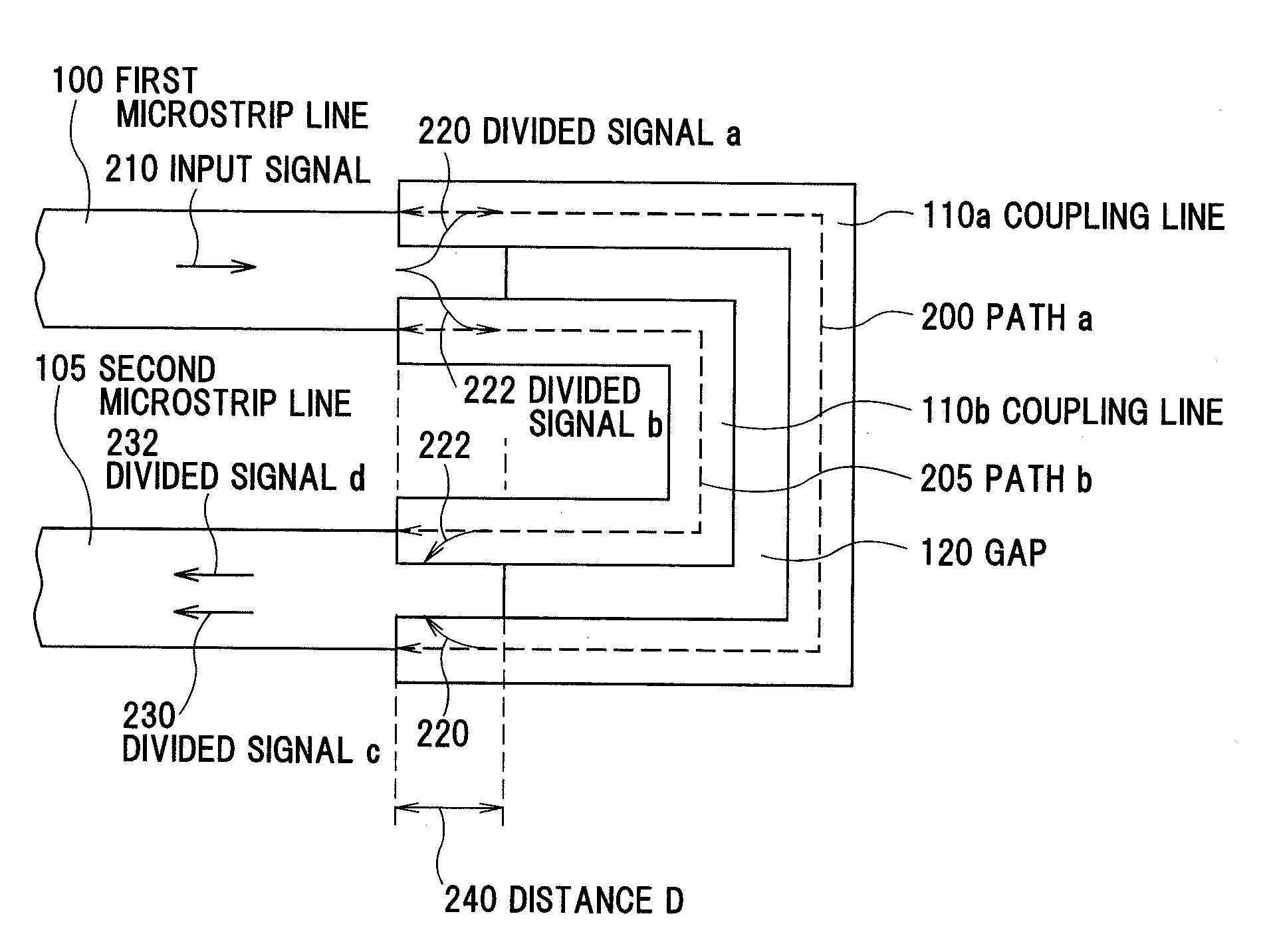
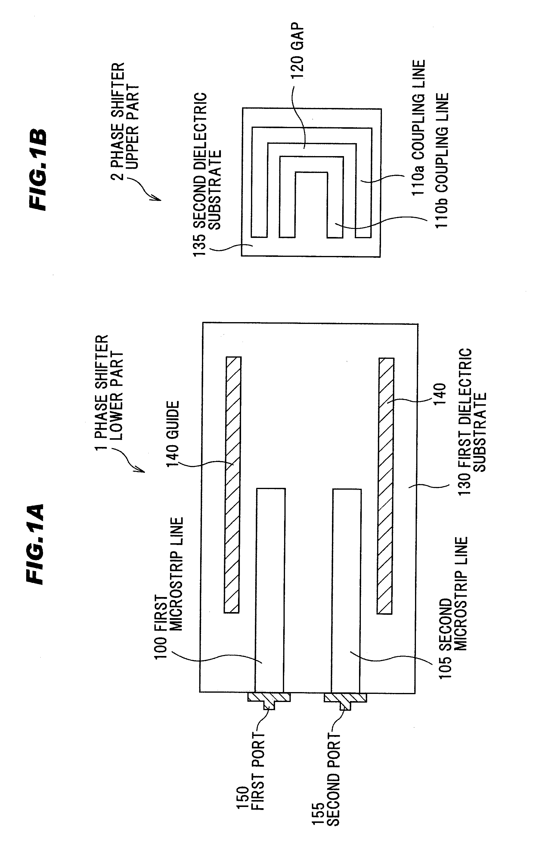
[0042]FIGS. 1A and 1B are plan views of a phase shifter upper part and a phase shifter lower part in a first preferred embodiment according to the present invention, in which FIG. 1A is a plan view of the phase shifter lower part in the first preferred embodiment, and FIG. 1B is a plan view of the phase shifter upper part in the first preferred embodiment.

[0043]In addition, FIG. 1B shows a phase shifter upper part 2 viewed from a side of a surface that is facing to a surface on which a first microstrip line 100 and a second microstrip line 105 provided at a phase shifter lower part 1 are formed.

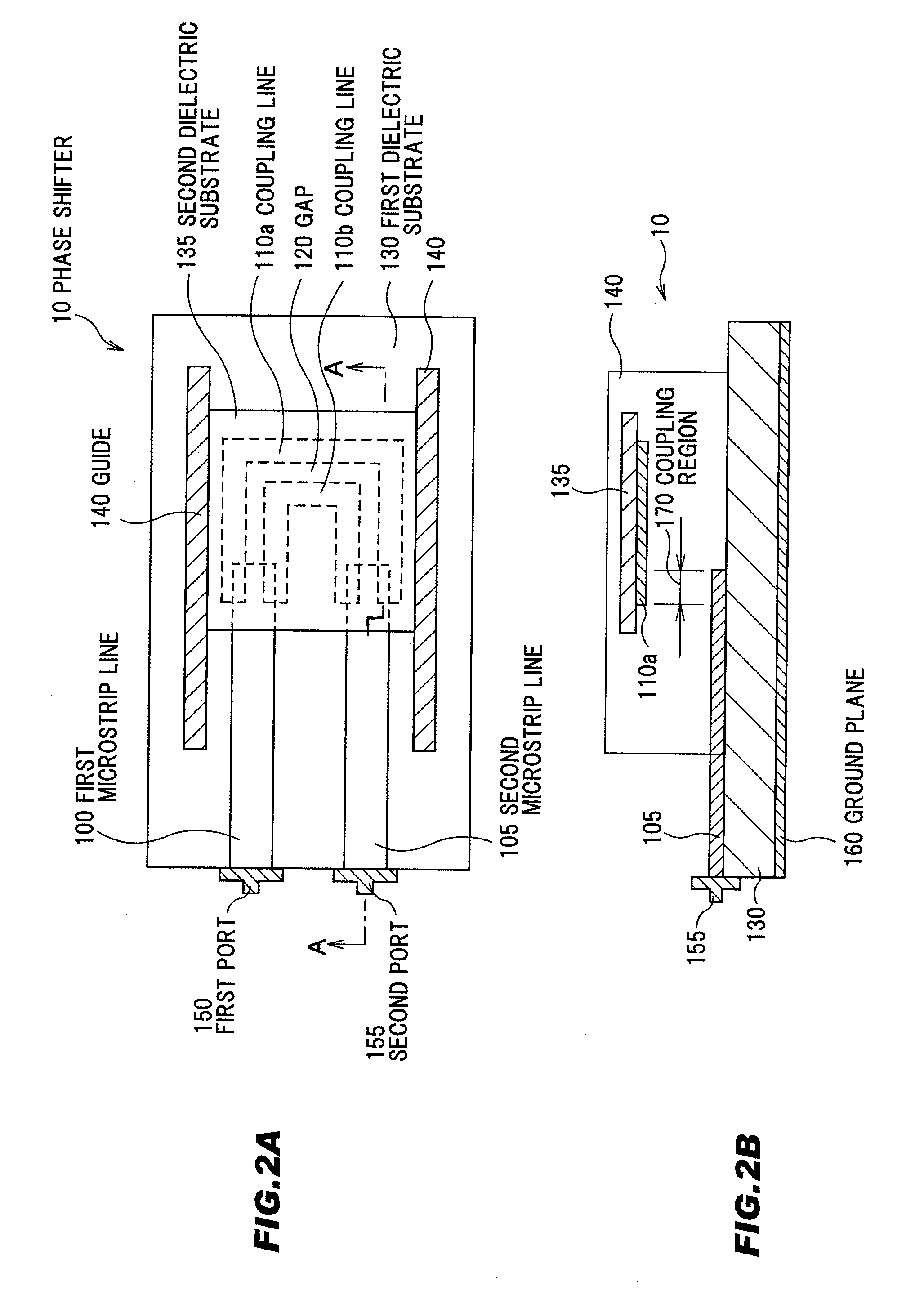
[0044](Structure of a Phase Shifter 10)

[0045]A phase shifter 10 in this preferred embodiment comprises the phase shifter lower part 1 and the phase shifter upper part 2.

[0046]The phase shifter lower part 1 comprises a first dielectric substrate 130, a first microstrip line 100 provided at a predetermined region on the first dielectric substrate 130 for transmitting a predetermined input signa...

second preferred embodiment

[0099]FIG. 7 is a schematic diagram showing an example of a structure of a phase shifter in a second preferred embodiment according to the present invention.

[0100]In FIG. 7, for the purpose of simplifying the explanation for the purpose of simplifying the explanation, illustration of several elements constituting the phase shifter 10, except the first microstrip line 100, the second microstrip line 105, the coupling line 110a, and the coupling line 110b, is omitted.

(Structure of the Phase Shifter 20)

[0101]In this preferred embodiment, a phase shifter 20 comprises a plurality of the phase shifters 10. Since the phase shifter 10 in the second preferred embodiment has substantially similar structure, function and effect to those of the phase shifter 10 explained in conjunction with FIGS. 1A to 5B, and FIGS. 6A to 6D, the detailed description of the phase shifter 10 is omitted here.

[0102]In concrete, the phase shifter 20 comprises an input terminal 500 to which a predetermined input sig...


PUM


Abstract

A first microstrip line 100 transmits a predetermined input signal. A coupling line includes a gap 120 along a transmitting direction of the input signal, and the gap 120 forms a plurality of paths having different path lengths. The input signal is divided by the gap 120 into divided signals. The paths are electrically coupled to the first microstrip line 100 at a first region to transmit the divided signals. A second microstrip line 105 is provided in parallel with the first microstrip line and electrically coupled to the coupling line at a second region. The second microstrip line 105 transmits each of the divided signals transmitted through the coupling line.

Description

[0001]The present application is based on Japanese Patent Application No. 2007-145340 filed on May 31, 2007, the entire contents of which are incorporated herein by reference.BACKGROUND OF THE INVENTION[0002]1. Field of the Invention[0003]The present invention relates to a phase shifter, in more particular, to a transmission line phase shifter.[0004]2. Related Art[0005]As a phase shifter used for beam control or phase modulation of a phased array antenna, a transmission line phase shifter has been conventionally used. For example, Japanese Patent Laid-Open No. 5-14004 discloses a phase adjustment circuit, comprising a first substrate, a U-shaped pattern formed on the first substrate, a second substrate, and first and second patterns formed on the second substrate, each of the first and second patterns having a part provided in parallel with each other, in which parallel parts in the U-shaped pattern are overlapped with the parallel patterns of the first and second patterns to contac...

Claims


Application Information

Patent Timeline
IPC IPC(8): H01P1/18
CPCH01P1/184
Inventor MURANO, SHINSUKI
Owner HITACHI LTD
Why Eureka
Try Eureka