Die attach methods and apparatus for micro-fluid ejection device

a technology of ejection device and die attachment, which is applied in the direction of printing, etc., can solve the problems of limited fluid passageway spacing in the ejection head substrate, small ejection head substrate, and difficulty in adequately segregating multiple fluids in the cartridge from one another, so as to reduce the cost of manufacture, reduce the size and increase the miniaturization effect of the operative par

Active Publication Date: 2006-06-01
FUNAI ELECTRIC CO LTD
View PDF10 Cites 5 Cited by
  • Summary
  • Abstract
  • Description
  • Claims
  • Application Information

AI Technical Summary

Benefits of technology

[0008] An advantage associated with at least some of the apparatus and methods disclosed herein is that multiple different fluids may be ejected from a micro-fluid ejection device that is less costly to manufacture and has dimensions that enable increased miniaturization of operative parts of the device. Continued miniaturization of the operative parts enables micro-fluid ejection devices to be used in a wider variety...

Problems solved by technology

However, the trend is to further miniaturize the ejection devices and thus provide even smaller ejection head substrates.
However, this trend leads to challenges relating to the attachment of such substrates to a multi-fluid supply reservoir.
As the ejection heads are reduced in size, it becomes increasingly difficult to adequately segregate multiple fluids in the cartridges from one another yet provide the fluids to different areas of the ejection heads.
One of the limits on spa...

Method used


Image

  • Die attach methods and apparatus for micro-fluid ejection device
  • Die attach methods and apparatus for micro-fluid ejection device
  • Die attach methods and apparatus for micro-fluid ejection device

Examples


Embodiment Construction

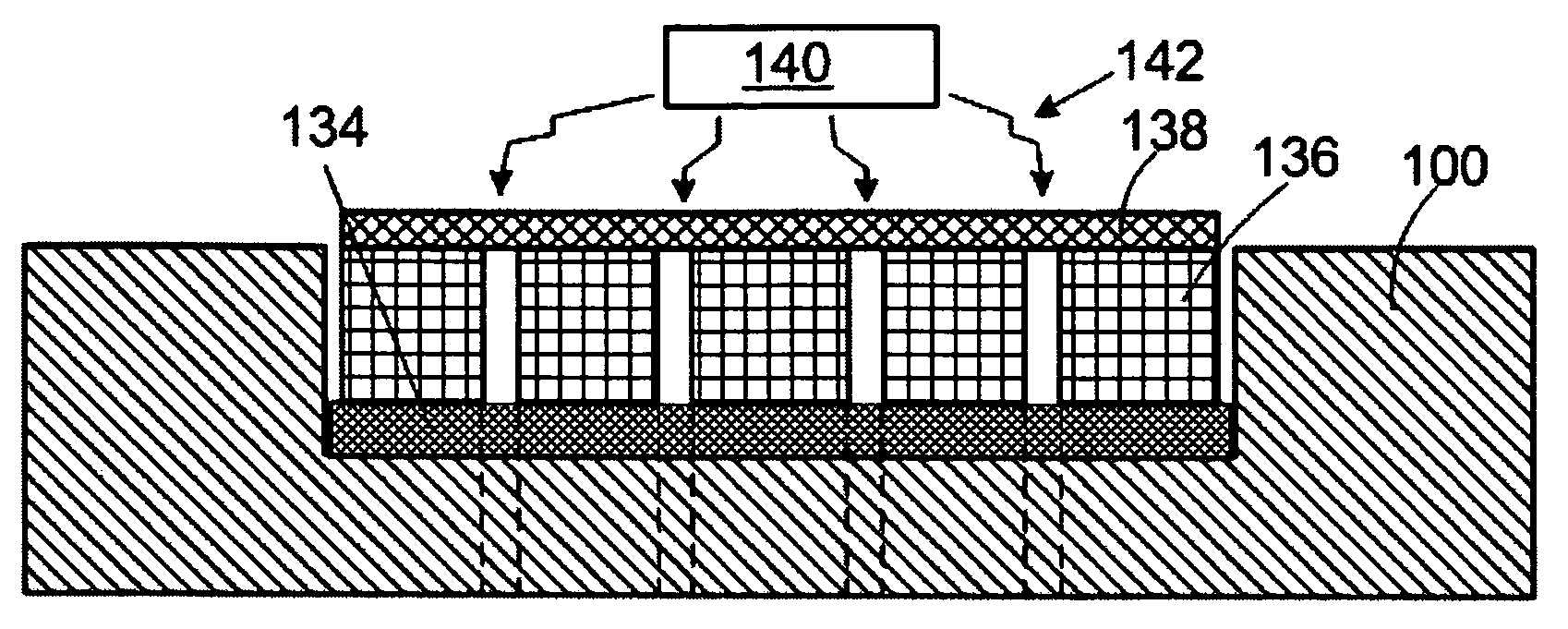
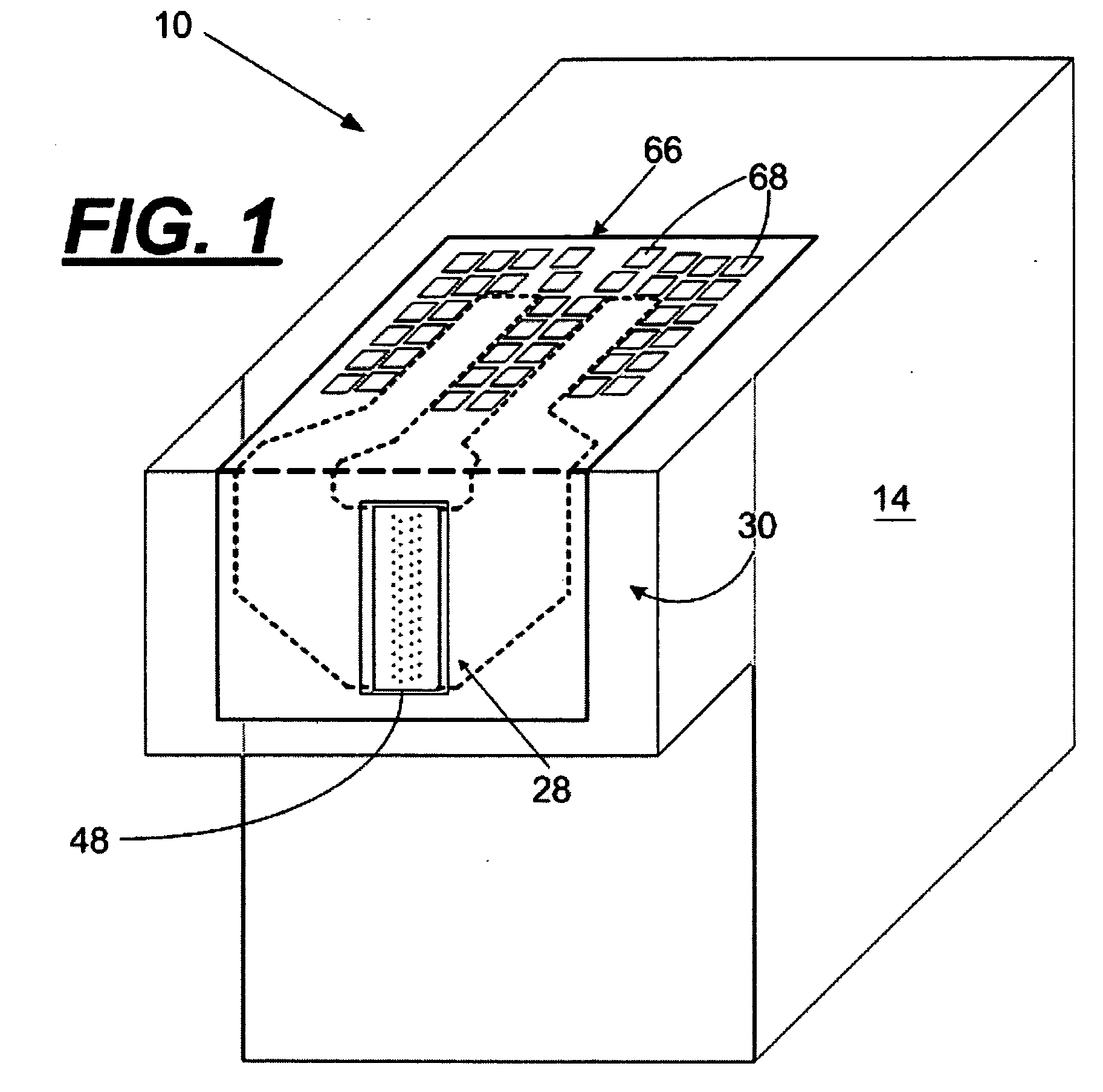
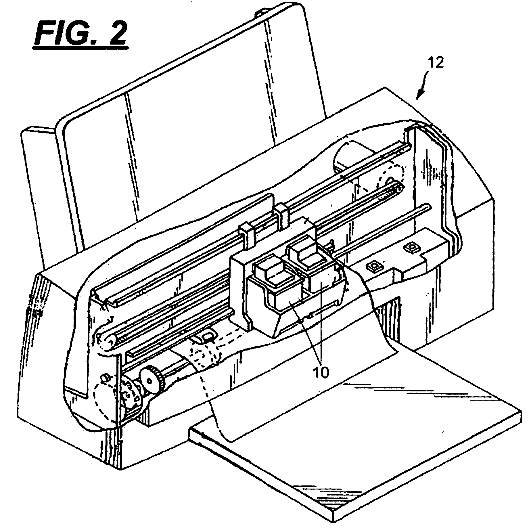
[0022] With reference to FIGS. 1-7, a multi-fluid cartridge body 10 (FIG. 1) for a micro-fluid ejection device, such as an ink jet printer 12 (FIG. 2) is illustrated. The multi-fluid body 10 includes a body structure 14 having exterior side walls 16, 18, 20, and 22 and a bottom wall 24 forming an open-topped, interior cavity 26 (FIGS. 3-6). An ejection head area 28 is disposed adjacent a portion 30 of the bottom wall 24 opposite the interior cavity 26. At least two segregated fluid chambers 32 and 34 are provided within the interior cavity 26 of the body structure 14. A dividing wall 36 separates chamber 32 from chamber 34. An additional dividing wall 38 may be provided to separate a third fluid chamber 40 from the chamber 32 for one of the cartridge bodies 10 containing three different fluids.

[0023] Independent fluid supply paths 42, 44, and 46 (FIGS. 4-5) are provided from each of the fluid chambers 32, 34, and 40 to provide fluid to an ejection head structure 48 attached adjacen...


PUM


Abstract

A micro-fluid ejection device structure, a multi-fluid cartridge containing the ejection device structure, and methods for making the ejection device structure and cartridge. The micro-fluid ejection device structure includes a fluid supply body containing at least three fluid supply slots therein. An ejection head substrate having fluid feed slots therein is attached to the fluid supply body. Each of the fluid supply slots in the body is in flow communication with at least one of the fluid feed slots in the substrate. A plurality of adhesive bond lines adhesively attach the ejection head substrate and the fluid supply body to one another. Each of the adhesive bond lines have a width of less than about 600 microns and are located between adjacent ones of the fluid supply slots in the body.

Description

FIELD OF THE DISCLOSURE [0001] The disclosure relates to micro-fluid ejection devices and in particular to structures and techniques for securing a semiconductor substrate to a multi-fluid reservoir. BACKGROUND AND SUMMARY [0002] In the field of micro-fluid ejection devices, ink jet printers are an exemplary application where miniaturization continues to be pursued. However, as micro-fluid ejection devices get smaller, there is an increasing need for unique designs and improved production techniques to achieve the miniaturization goals. For example, the increasing demand of putting more colors in a single inkjet cartridge requires the addition of fluid flow passageways from the cartridge body to the ejection head that, without radical changes in production techniques, will require larger ejection head substrates. However, the trend is to further miniaturize the ejection devices and thus provide even smaller ejection head substrates. An advantage of smaller ejection head substrates i...

Claims


Application Information

Patent Timeline
IPC IPC(8): B41J2/175
CPCB41J2/17513B41J2/1753
Inventor BERTELSEN, CRAIG M.KWAN, KIN M.WEAVER, SEAN T.
Owner FUNAI ELECTRIC CO LTD
Why Eureka
Try Eureka