Cleaning device of vehicle lamp

a cleaning device and vehicle lamp technology, applied in vehicle maintenance, vehicle cleaning, lighting and heating apparatus, etc., can solve the problem of small amount of cleaning liquid between the check valve and the nozzle when the check valve is closed, and achieve the effect of smooth operation of the valve body and small vertical size of the overall devi

Inactive Publication Date: 2006-06-01
KOITO MFG CO LTD
View PDF7 Cites 21 Cited by
  • Summary
  • Abstract
  • Description
  • Claims
  • Application Information

AI Technical Summary

Benefits of technology

[0015] In addition, since the valve body is disposed such that its radial direction is parallel to the sliding direction of the piston, if an arrangement is provided such that the sliding direction of the piston substantially conforms to the back-and-forth direction, and such that the radial direction of the valve body becomes substantially horizontal, the vertical size of the overall device can be made small. As a result, the cleaning device can be disposed in a small space on the upper or lower side or on the left or right side along the periphery of the vehicle lamp. In addition, since the check valve is disposed at the front end of the piston, i.e., immediately in front of the nozzle, when the injection of the cleaning liquid is stopped, the amount of the cleaning liquid remaining between the check valve and the nozzle is very small, and the cleaning liquid practically does not leak from the nozzle when the device is not in use.
[0016] Moreover, in accordance with one or more embodiments of the present invention, the valve disposing portion may include: a valve body accommodating recess communicating with the cleaning liquid efflux portion and having an air hole communicating with an outside, wherein the valve body accommodating recess is arranged in the direction substantially perpendicular to the sliding direction of the piston; a pressure forming portion communicating with the cleaning liquid influx portion, wherein the pressure forming portion is arranged in the direction substantially perpendicular to the sliding direction of the piston; and a communicating hole for communicating the valve body accommodating recess and the pressure forming portion. In addition, the valve body is accommodated in the valve body accommodating recess so as to divide the communicating hole and the cleaning liquid efflux portion and the air hole. Moreover, when the pressure of the cleaning liquid is increased in the pressure forming portion, the valve body moves toward the air hole, so that the pressure forming portion and the cleaning liquid efflux portion are communicated with each other. Accordingly, the operation of the valve body is effected smoothly.

Problems solved by technology

Moreover, the amount of the cleaning liquid remaining between the check valve and the nozzle when the check valve is closed is small.

Method used


Image

  • Cleaning device of vehicle lamp
  • Cleaning device of vehicle lamp
  • Cleaning device of vehicle lamp

Examples


Embodiment Construction

[0037] Embodiments of the invention will be described with reference to the accompanying drawings.

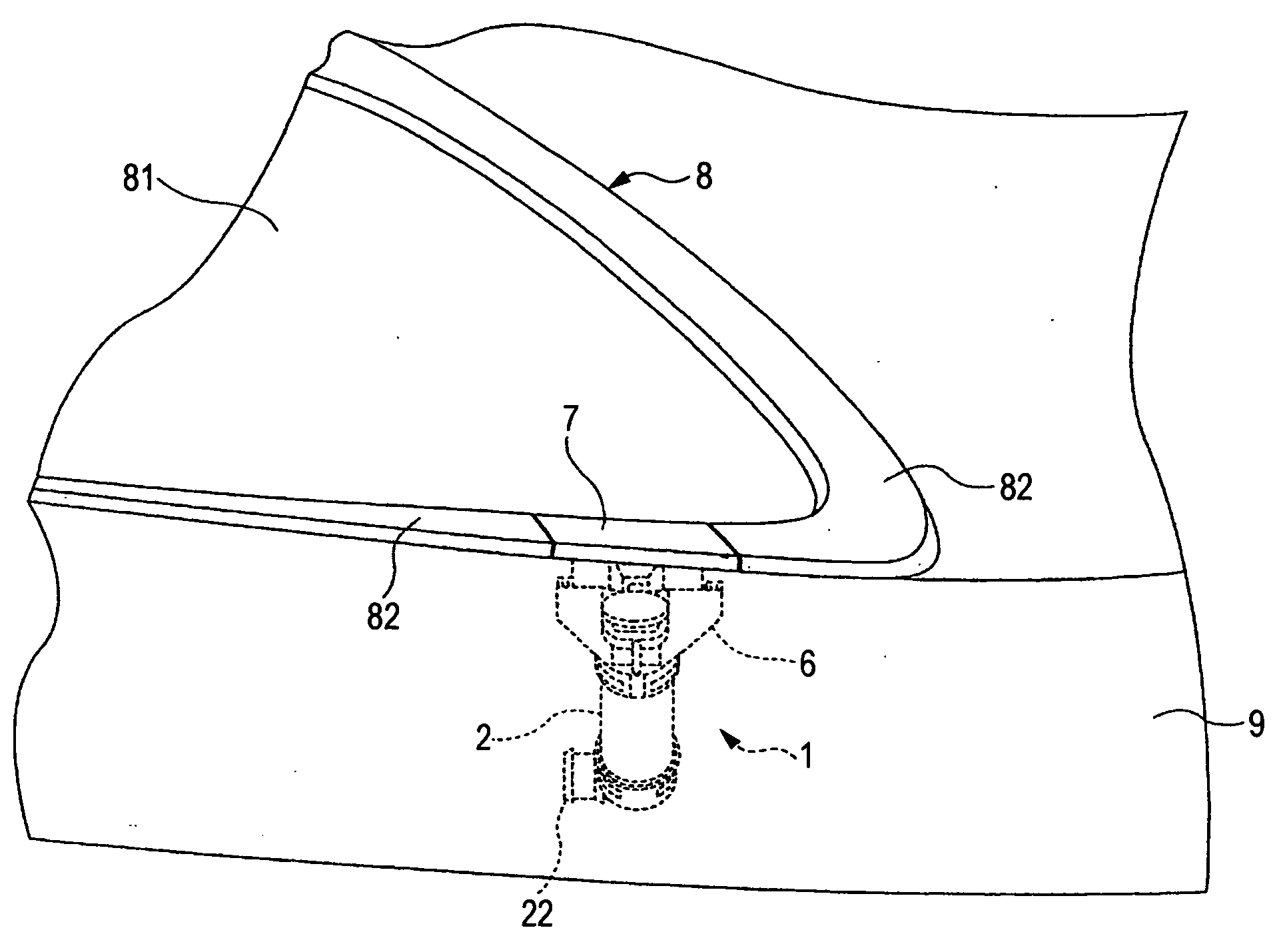
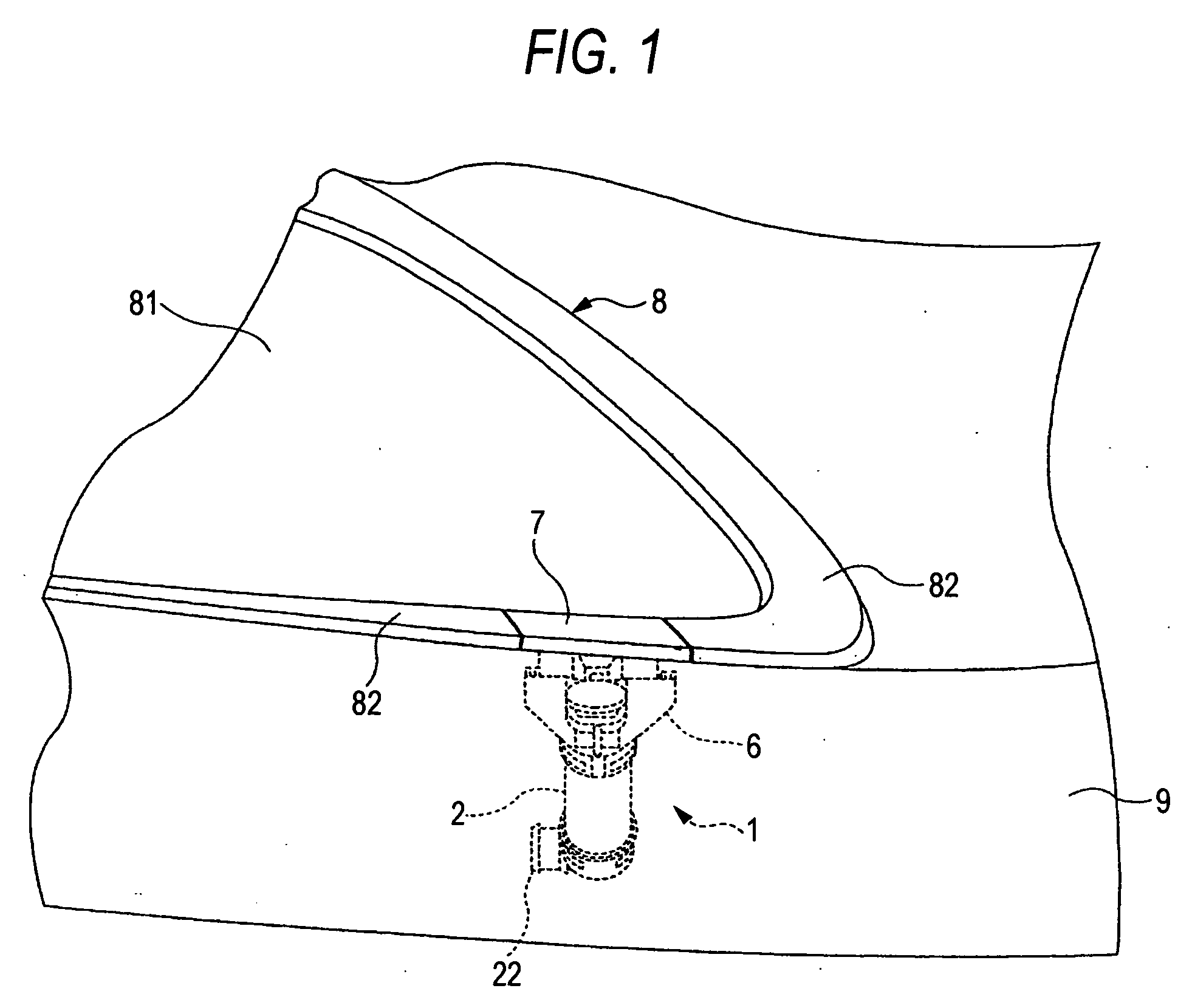
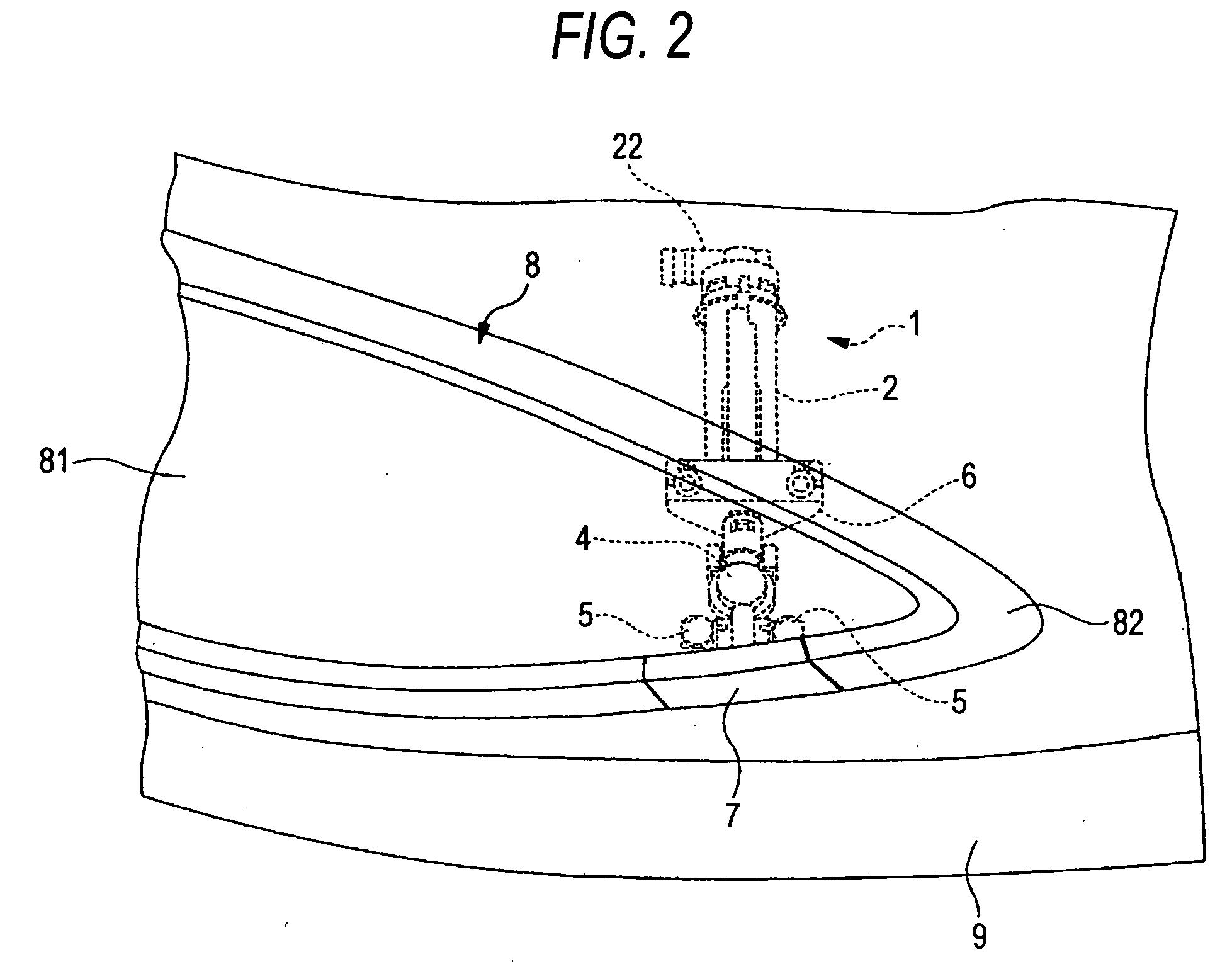
[0038] A cleaning device 1 for a vehicle lamp is structured by a cylinder 2; a piston 3 slidably coupled to the cylinder 2; and a nozzle 5 connected to a distal end of the piston 3 through a check valve 4.

[0039] The cylinder 2 has a substantially tubular main portion 21 and a joint portion 22 for closing a rear end of the main portion 21.

[0040] A plurality of engaging projections 21a and 21b (see FIGS. 3 and 4) are respectively formed on a front end portion and a rear end portion on an outer peripheral surface of the main portion 21 at intervals in the circumferential direction. In addition, an inwardly projecting inner flange 21c (see FIG. 5) is formed in a front end of the main portion 21.

[0041] The joint portion 22 has a substantially annular shape, and is constructed such that a fitting portion 221 whose rear end is closed and a connecting tube 222 connected to a rear end of the...


PUM


Abstract

A check valve of a cleaning device of a vehicle lamp is provided with a cleaning liquid influx portion, a valve disposing portion, and a cleaning liquid efflux portion which are arranged in series in a sliding direction of the piston. A valve body is disposed in the valve disposing portion. The valve body opens and closes a space between the cleaning liquid influx portion and the cleaning liquid efflux portion, when at least a portion of the valve body moves in a direction substantially perpendicular to a sliding direction of a piston.

Description

[0001] The present application claims foreign priority based on Japanese Patent Application No. P.2004-343733, filed on Nov. 29, 2004, the contents of which are incorporated herein by reference. BACKGROUND OF THE INVENTION [0002] 1. Field of the Invention [0003] The present invention relates to a cleaning device for a vehicle lamp. More particularly, the present invention relates to a technique for downsizing an overall cleaning device in a direction perpendicular to the sliding direction of a piston. [0004] 2. Related Art [0005] A vehicle lamp, such as a headlamp, is an important functional part in a vehicle. Therefore, an impairment of a beam illumination capability should be avoided. [0006] One cause of the impairment of the illumination capability of the vehicle lamp such as a headlamp is a staining of a front lens. For example, during traveling on an unpaved road at the time of a rainfall or snow thawing, muddy water splashed by an own vehicle, a preceding vehicle, or an oncomi...

Claims


Application Information

Patent Timeline
Patent Type & Authority Applications(United States)
IPC IPC(8): F21V33/00
CPCB60S1/528B60S1/56B60S1/46B60S1/60
Inventor SAKAI, MASARUSATO, MASAAKI
Owner KOITO MFG CO LTD
Why Eureka
Try Eureka