
Internal bubble cooling unit for extruded thin wall thermoplastic sheet

a thermoplastic sheet and bubble cooling technology, applied in the direction of ceramic shaping apparatus, manufacturing tools, etc., can solve the problems of melting or roughening of the film surface, etc., and reducing the effective cooling capability. , the effect of slowing the output of the entire production process

Inactive Publication Date: 2006-06-01
HATFIELD ERIC
View PDF4 Cites 1 Cited by
  • Summary
  • Abstract
  • Description
  • Claims
  • Application Information

AI Technical Summary

Benefits of technology

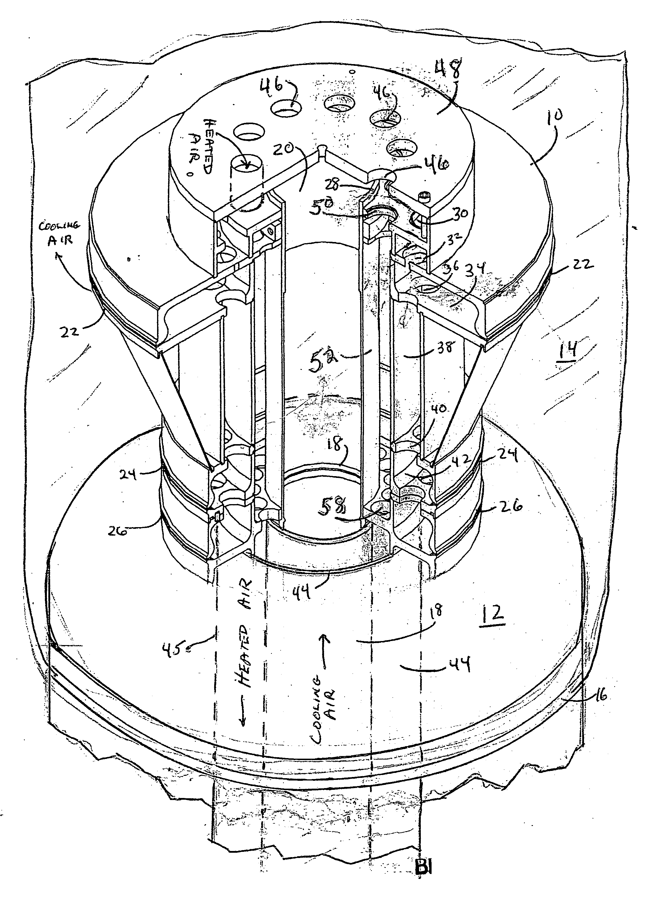
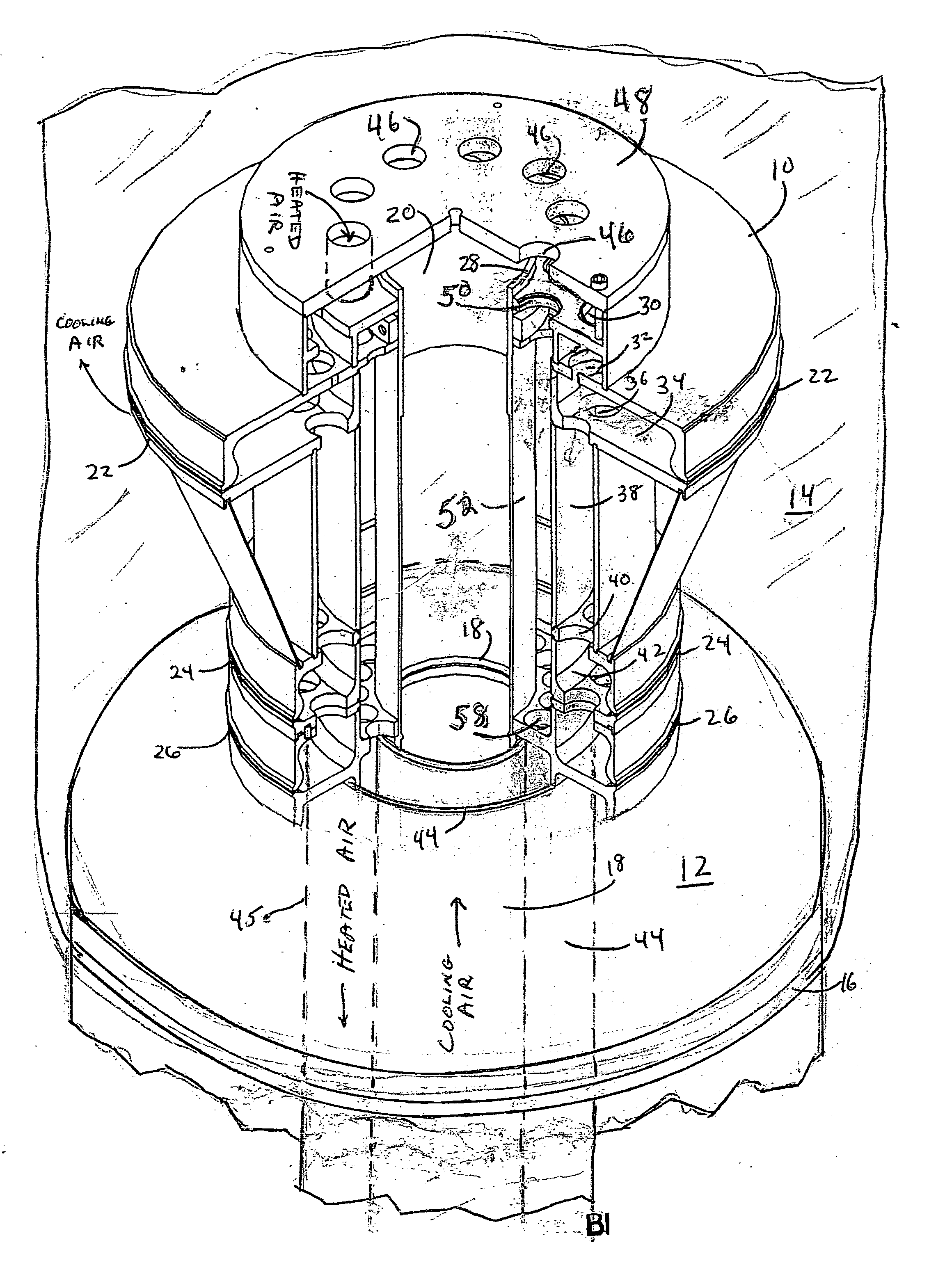
The invention is an apparatus and method for cooling thin wall thermoplastic sheet produced in the form of an extruded tubular bubble from an annular die head. The invention achieves several advantages over prior art devices. First, cooling air is delivered to the interior of the bubble by a central pipe, channel, or similar conduit and heated air is withdrawn from the bubble by an additional separate conduit positioned between the central pipe and the die head, which prevents heat transfer from the die to the cooling air stream and ensures effective cooling capability. Second, the cooling air stream is positioned away from the die, which prevents die cooling and avoids melt fracture or uneven film thickness. Third, the invention eliminates the need for notching or putting a flat spot in the outer pipe to allow for wires, which can affect cooling airflow and cause uneven film thickness.

Problems solved by technology

In the prior art devices where the cooling air conduit is adjacent to the inner die wall, there is some transfer of heat from the die to the cooling air stream raising the cooling air stream temperature reducing the effective cooling capability thus slowing the output of the entire production process.
Additionally, when the cooling air stream is adjacent to the die, the die itself is cooled which can cause, among other things, melt fracture or a roughening of the film surface.
This can upset the cooling airflow making it non-uniform around the circumference of the die.
This may result in uneven film thickness presenting difficulties with further use of the product.

Method used


Image

  • Internal bubble cooling unit for extruded thin wall thermoplastic sheet
  • Internal bubble cooling unit for extruded thin wall thermoplastic sheet

Examples


Embodiment Construction

[0015] Referring first to FIG. 1, there is illustrated a perspective view of the preferred embodiment of the invention. Cooling tower 10 is shown mounted forward or atop of die head 12 which is supplied with an appropriate heated thermoplastic material by an extruder, not shown. In the process, die head 12 produces a continuous thin walled thermoplastic tubular bubble 14. Bubble 14, which completely surrounds tower 10, emerges in a heated state from slit port 16 extending completely around die head 12.

[0016] The material is then cooled to ambient temperature to allow take off and further processing. A standard procedure is to provide a flow of cooling air to the interior of the bubble while simultaneously removing air heated by the cooling process. This has been accomplished in the past by the use of conduits such as pipes, ducts, channels, and the like extending through the die head and cooling tower. The prior art practice is to employ a coaxial arrangement in which the outermost...


PUM

PropertyMeasurementUnit
temperatureaaaaaaaaaa
mechanical parametersaaaaaaaaaa
circumferenceaaaaaaaaaa

Abstract

An internal bubble cooling apparatus for cooling extruded thermoplastic thin wall tubular bubbles emanating from an extrusion die head employing a first central channel for introducing cooling air into the bubble and a second channel formed between the outer wall of the central channel and the inner wall of the die head for withdrawing heated air from the bubble. Integration of the die head and airflow channels with a cooling tower and the method of use are also disclosed.

Description

CROSS REFERENCE TO RELATED APPLICATIONS [0001] This application is a divisional application of U.S. Ser. No. 10 / 672,560 filed Sept. 29, 2003 of the same title by the same inventor.BACKGROUND OF THE INVENTION [0002] 1. Field of the Invention [0003] The invention resides in the field of apparatus and methods for the extrusion of thin wall thermoplastic sheet and more particularly relates to cooling the sheet as it emerges from the extrusion die. [0004] 2. Description of the Prior Art [0005] The extrusion of thin wall thermoplastic sheet for use, for example, as wrapping and bagging products is well known in the prior art. The technique employed is to utilize an annular extrusion die fed by an extruder of molten thermoplastic material to produce a tubular bubble which is then cooled and drawn off for use in manufacturing finished goods. [0006] In the process, a step known as internal bubble cooling is accomplished by placing a cooling tower forward of the die which acts as a heat excha...

Claims


Application Information

Patent Timeline
Patent Type & Authority Applications(United States)
IPC IPC(8): B29C47/88B29C35/16B29C48/08B29C48/10
CPCB29C47/0021B29C47/883B29C2035/1666B29C48/08B29C48/10B29C48/9125
Inventor HATFIELD, ERIC
Owner HATFIELD ERIC
Learn More