
Ceiling air-blowing device for a vehicle air conditioner

Inactive Publication Date: 2006-06-01
UMEBAYASHI MAKOTO +1
View PDF5 Cites 1 Cited by
  • Summary
  • Abstract
  • Description
  • Claims
  • Application Information

AI Technical Summary

Benefits of technology

[0009] It is further another object of the present invention to provide a ceiling air-blowing device for a vehicle air conditioner capable of easily adjusting flow direction of air from a ceiling of the vehicle.
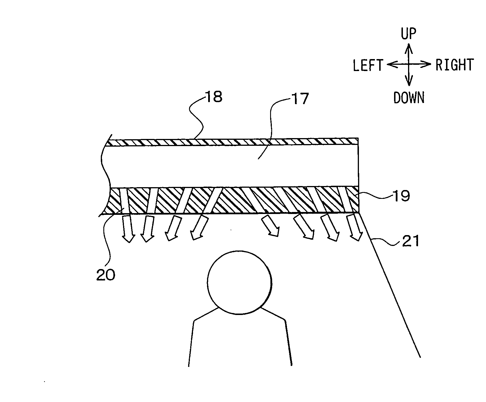
[0011] Accordingly, even if pressure loss is caused in the air passage, a volume of air blown from the holes of the second position is larger than a volume of air blown from the holes of the first position. Therefore, the blowing of air from the holes of the second position is facilitated as compared with that of the first position. As a result, the air is relatively uniformly blown from a wide range of the ceiling portion.
[0013] Accordingly, since the air flow directions from the holes are varied in accordance with the distance from the end of the duct, the air can be relatively uniformly blown from a wide range of the ceiling portion even if the size of the holes are uniform. Therefore, it improves an air-conditioning that a passenger fells comfortable.

Problems solved by technology

When the cooling load is low, however, the cool air that is partly blown from the ceiling causes passenger discomfort.
Further, because this structure causes variation of flow velocity and temperature, it is difficult to provide an air-conditioning that the passenger feels comfort.
However, size of the holes and air blowing directions are not proposed in JP-U-62-3310.
Accordingly, it is difficult to provide an air-conditioning uniformly over a wide range of the passenger compartment.

Method used


Image

  • Ceiling air-blowing device for a vehicle air conditioner
  • Ceiling air-blowing device for a vehicle air conditioner
  • Ceiling air-blowing device for a vehicle air conditioner

Examples


first embodiment

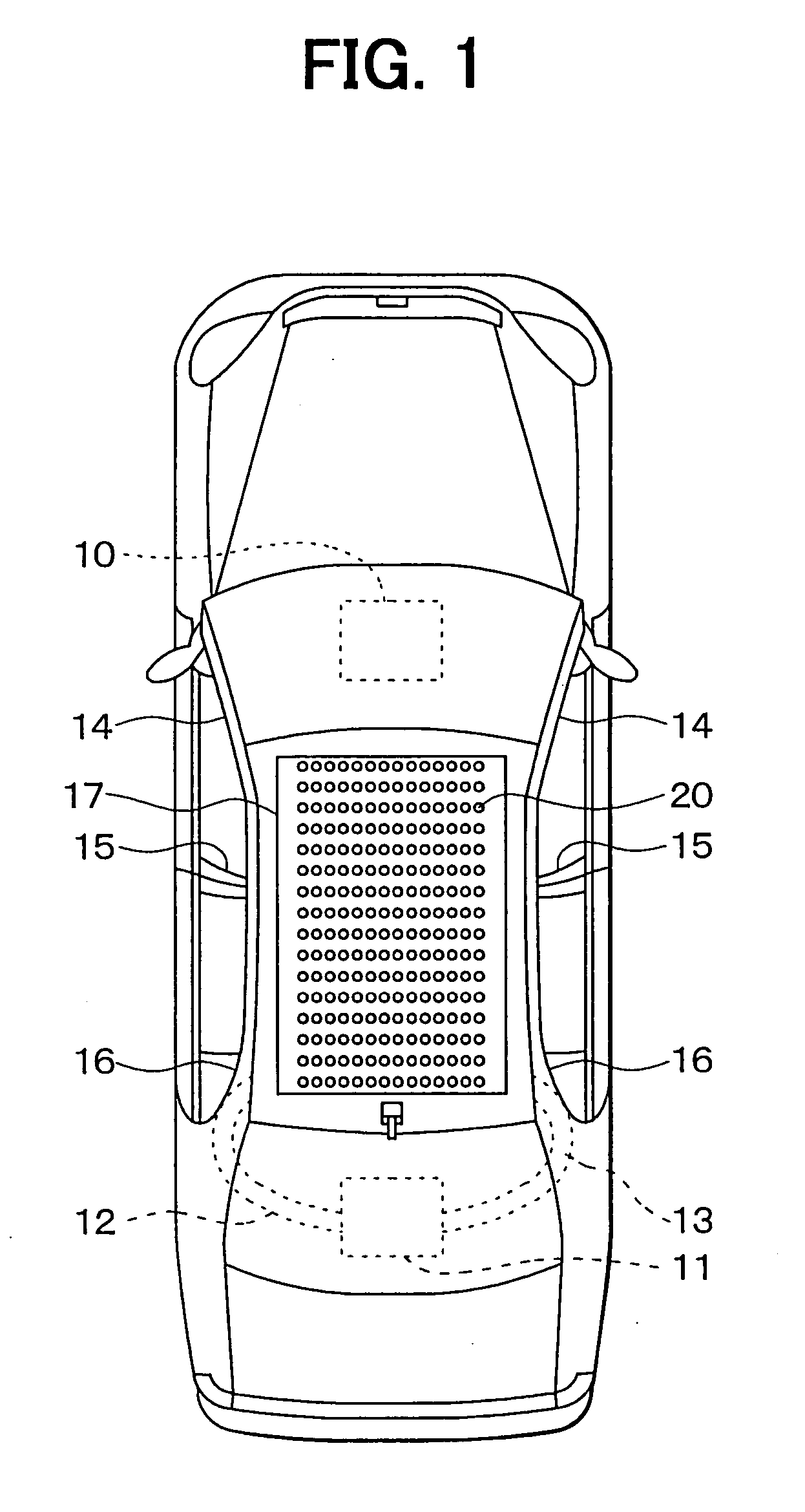
[0035] Referring to FIG. 1, a vehicle air conditioner includes a front air conditioner unit 10 and a rear air conditioner unit 11, as interior air conditioner units. The front air conditioner unit 10 is arranged in a space inside of an instrument panel, which is located at a very front position of a passenger compartment. The front air conditioner unit 10 air-conditions a front region of the passenger compartment. The rear air conditioner unit 11 is arranged under a luggage compartment lid, which is located at a very rear position of the passenger compartment. The rear air conditioner unit 11 air-conditions a rear region of the passenger compartment.

[0036] The front and rear air conditioner units 10, 11 have electric blowers, cooling heat exchangers for cooling air blown by the blowers, heating heat exchangers for heating the air, temperature setting devices for setting temperature of air blown into the passenger compartment, air blow mode switching devices, and the like, respectiv...

second embodiment

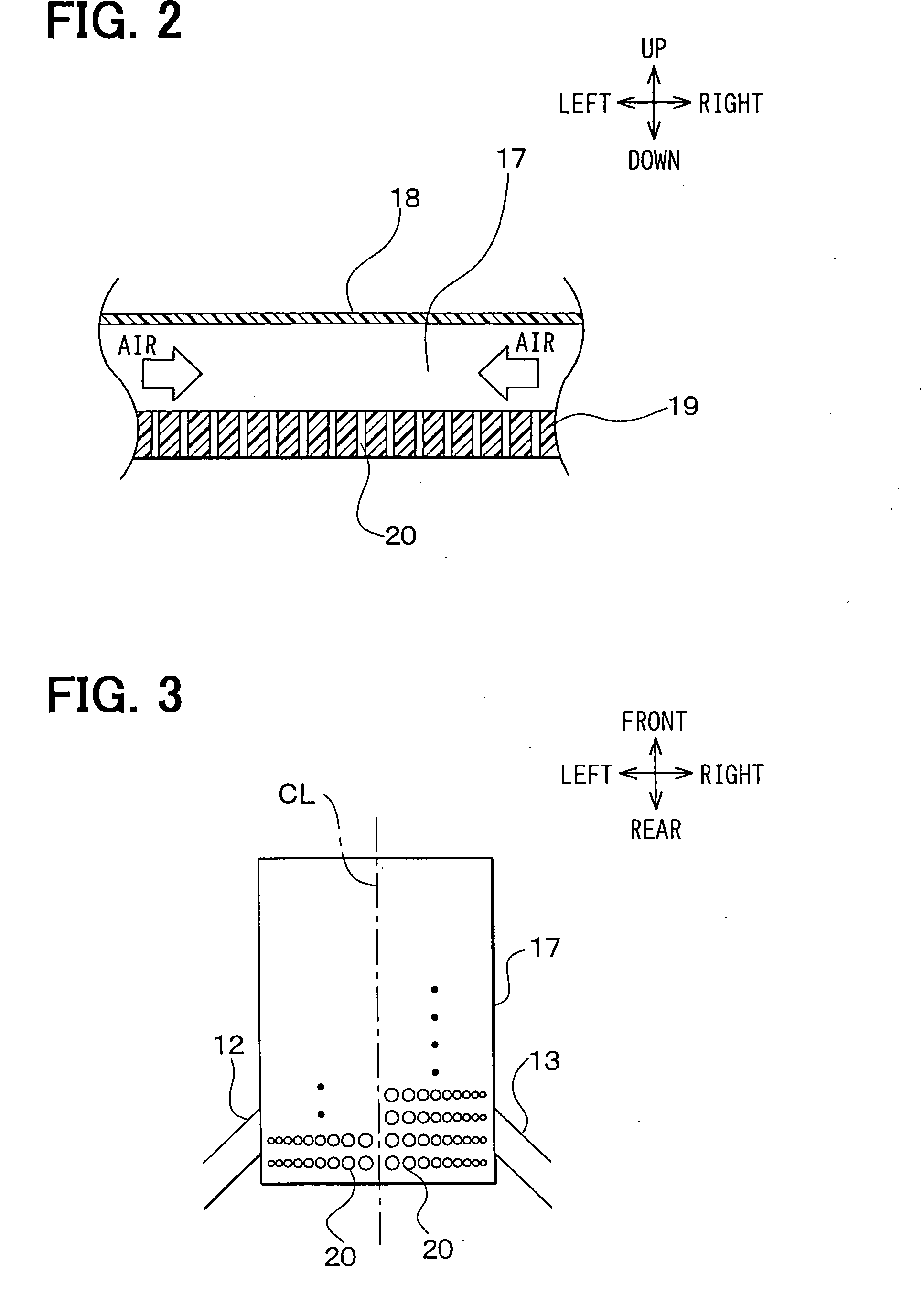
[0054] Referring FIG. 5, the size of the holes 20 is varied with respect to the front and rear direction of the ceiling in the second embodiment. That is, the area of the openings of the holes 20 at a rear position that is proximate to the end of the pillar ducts 12, 13 is small. The area of the opening of each hole 20 increases toward the front position of the ceiling.

[0055] Accordingly, the volume of air passing through the holes 20 at the rear position is reduced by reducing the area of the openings. Also, the volume of air passing through the hole 20 is increased with a distance from the rear position by increasing the area of the openings. Therefore, the flow velocity of air is uniformed with respect to the front and rear direction of the ceiling.

third embodiment

[0056] Referring FIG. 6, the area of the openings of the holes 20 is varied with respect to both of the front and rear direction and the right and left direction of the ceiling in the third embodiment. The area of the opening of the hole 20 that is located proximate to the right / left end and the rear end of the ceiling is the smallest. The area of the opening of the hole 20 is gradually increased toward the middle position CL and the front position of the ceiling. Accordingly, the flow velocity of the air passing through the holes 20 is uniformed with respect to the front and rear direction and the right and left direction of the ceiling.


PUM


Abstract

In the ceiling air-blowing device for a vehicle air conditioner, a ceiling wall is disposed along a vehicle ceiling portion to define an air passage so that air from an air conditioner unit is introduced into the air passage through a pillar duct. The ceiling wall is formed with a plurality of holes having openings on a lower surface of the ceiling wall, so that the air in the air passage is blown off into the passenger compartment through the holes. Further, the holes are formed such that a total area of the openings of the holes per unit area at a position that is proximate to the end of the duct is smaller than that at a second position that is farther from the end of the duct than the first position. Therefore, the air is uniformly blown into the passenger compartment over a wide range of the ceiling.

Description

CROSS-REFERENCE TO RELATED APPLICATIONS [0001] This application is a divisional of U.S. patent application Ser. No. 10 / 701,320 filed on Nov. 4, 2003. This application claims the benefit of Japanese Patent Application No. 2002-322666 filed Nov. 6, 2002, the disclosures of which are incorporated herein by referenced.FIELD OF THE INVENTION [0002] The present invention relates to a ceiling air-blowing device for a vehicle air conditioner, which produces flow of air from holes formed on a ceiling of a vehicle for air-conditioning a passenger compartment. BACKGROUND OF THE INVENTION [0003] With regard to a conventional ceiling air-blowing device for a vehicle air conditioner, a grille through which air is blown into a passenger compartment is provided at a part of a ceiling such as at a side, front portion or rear portion of the ceiling. Thus, air is partly blown toward a passenger. [0004] When a cooling load is high, since a cool air is blown from the part of the ceiling, a cold feeling ...

Claims


Application Information

Patent Timeline
IPC IPC(8): B60H1/00B60H1/24B60H1/34
CPCB60H1/247B60H1/3407
Inventor UMEBAYASHI, MAKOTOINADA, TOMOHIRO
Owner UMEBAYASHI MAKOTO
Learn More