
Fault detection diagnostic variable differential variable delay thermostat

a technology of delay thermostat and diagnostic variable, which is applied in the direction of heating types, lighting and heating apparatus, instruments, etc., can solve the problems of nest thermostat not providing a fan-only heating method, not being able to vary, and still turning on if, so as to achieve the effect of improving energy efficiency

Active Publication Date: 2020-07-14
LAU JAMES
View PDF69 Cites 8 Cited by
  • Summary
  • Abstract
  • Description
  • Claims
  • Application Information

AI Technical Summary

Benefits of technology

[0059]The present invention provides a variable fan-off delay for cooling or heating based on a measured Conditioned Space Temperature (CST) providing a reliable variable fan-off delay that does not cause short AC compressor cycling and is not dependent on relative humidity to ensure occupant comfort, extend the air conditioning or heating equipment off cycle and improve energy efficiency.
[0067](1) monitoring, detecting, and reporting a Fault Detection Diagnostic (FDD) alarm short cycle message, and providing a variable cooling or heating differential temperature or a differential offset above or below the thermostat setpoint based on at least one HVAC parameter selected from the group consisting of: a heating cycle duration P3, a cooling cycle duration P4, and an off-cycle time P11 to control the heating cycle duration or the cooling cycle duration to avoid or correct short cycling and improve energy efficiency and thermal comfort;(2) recovering latent evaporative cooling energy from an air conditioning evaporator coil after the air conditioner has operated for sufficient time to condense enough water vapor on the evaporator coil to deliver enough sensible cooling to the conditioned space to increase thermal comfort, extend the air conditioning off cycle and improve energy efficiency;(3) energizing an HVAC fan to a higher fan speed than the lower heating fan speed during the heating cycle to increase airflow and heating energy delivered to the conditioned space and satisfy the thermostat call for heating in less time to save heating energy, increase thermal comfort, and improve energy efficiency;(4) recovering heating energy from a gas furnace, heat pump, hydronic or electric resistance heat exchanger after the heating system has operated for sufficient time to increase the heat exchanger temperature enough to deliver enough heating energy to the conditioned space to increase thermal comfort, extend the heating equipment off cycle and improve energy efficiency;(5) performing a Fault Detection Diagnostic (FDD) procedure comprising monitoring, detecting, reporting a FDD alarm fan-on message, and overriding a fan-on setting and turning off an HVAC fan is operating continuously by itself for longer than a Threshold Fan-on Time (TFT); and(6) providing a continuous Heat Pump (HP) reversing valve signal throughout a cooling cycle duration plus a fan-off delay duration or a heating cycle duration plus a fan-off delay duration to provide maximum cooling or heating capacity and energy efficiency.

Problems solved by technology

While Airwave requires the humidity level inside your home to be relatively low, it may still turn on if it's humid outside.
Furthermore, the Nest thermostat does not provide a fan-only heating method.
The Matsouka '805 “small fixed value” of 0.1° F. doesn't vary and doesn't provide sufficient control for all cooling conditions.
Furthermore, the Matsuoka '805 does not disclose any method for a variable fan-off delay for heating.
Nor does Matsuoka '805 disclose a method for determining a variable fan-off delay for cooling on the temperature measured during the current variable fan-off delay period compared to temperature measurements monitored during the current variable fan-off delay period.
Further, by measuring the current flow through the power buses to one or more of the solid state relays of the control device, potentially damaging over current conditions can be distinguished from permissible transient over-current conditions and the control device can deactivate any solid state relays which would be damaged while allowing solid state relays which are experiencing allowable transients to remain operating.
In the case of a severe over current condition, a current monitoring device can issue a fault signal, triggering an interrupt condition which will cause a processor in the controller to shut down the affected solid state relays very quickly.
The “burner on” signal is generally inaccessible by technicians and cannot be monitored from thermostat or equipment terminals.
For furnace operation less than 4 minutes, Adams '060 wastes fan energy and causes thermal comfort issues by circulating unwarmed air into the conditioned space before the heat exchanger is hot enough to provide satisfactory operating temperatures.
Therefore, Adams '060 effectively only provides a fixed-fan-off time delay of 4 minutes since all furnaces require at least 4 minutes of time to reach operating temperature and store enough heat to support a longer fan-off time delay.
Byrnes teaches control of the heater fan from low to high speed but the high speed is limited specifically to the motor speed used for heating which is low, medium, or medium high and not the motor's high speed used for cooling.
Byrnes' does not teach a variable fan-off time delay based on AC compressor or heat source operational time.
However, the Proctor 2008a was not disseminated or made available to the extent that persons interested and ordinarily skilled in the subject matter or art, exercising reasonable diligence, could locate the reference.
If the temperatures still have not changed in the way predicted, the reversing valve is still improperly positioned.
Prior art thermostats do not provide solutions to meet these unresolved needs.

Method used


Image

  • Fault detection diagnostic variable differential variable delay thermostat
  • Fault detection diagnostic variable differential variable delay thermostat
  • Fault detection diagnostic variable differential variable delay thermostat

Examples


Embodiment Construction

[0084]The following description is of the best mode presently contemplated for carrying out the invention. This description is not to be taken in a limiting sense, but is made merely for the purpose of describing one or more preferred embodiments of the invention. The scope of the invention should be determined with reference to the claims.

[0085]Where the terms “about” or “generally” are associated with an element of the invention, it is intended to describe a feature's appearance to the human eye or human perception, and not a precise measurement.

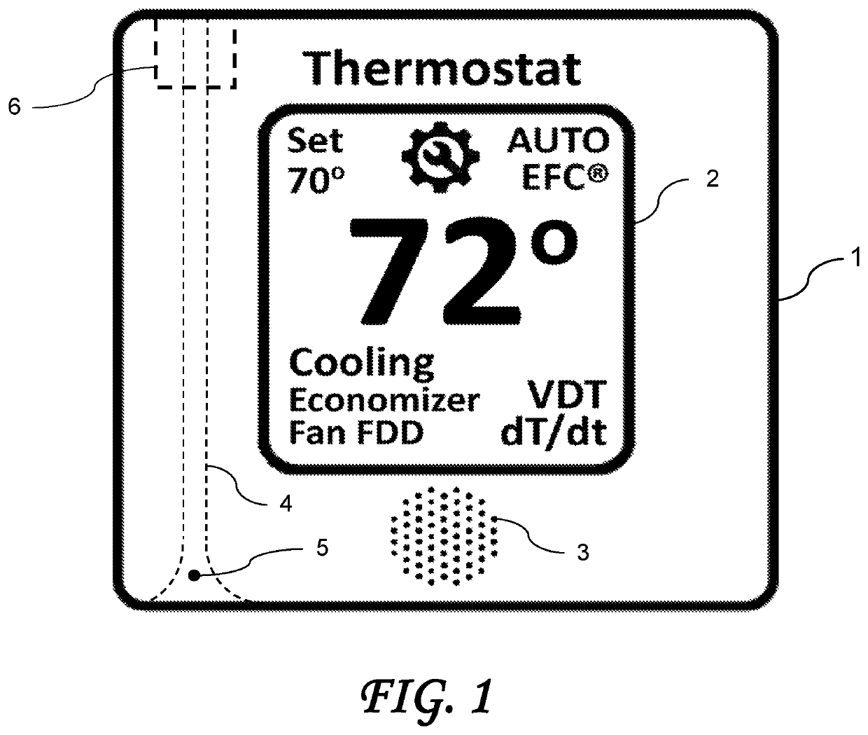
[0086]FIG. 1 shows a thermostat 1 used to control an HVAC unit. The thermostat 1 includes a display 2 providing a Variable Differential Temperature (“VDT”) control option to improve cooling or heating system efficiency by varying the cooling or heating differential to correct for short cycle events and lengthen on-cycles to increase thermal comfort and energy efficiency, save energy and extend the service life of the equipment. According t...


PUM


Abstract

A Fault Detection Diagnostic (FDD) variable differential and variable fan-off delay Heating Ventilating Air Conditioning (HVAC) thermostat control method. The FDD method detects a fan-on setting, reports a FDD fan-on alarm, overrides a fan-on setting, and turns off an HVAC fan. The FDD method detects, reports, and corrects a short-cycle by providing a variable differential based on: a cooling or heating cycle duration, or an off-cycle time. The variable fan-off delay is based on: a Conditioned Space Temperature (CST), comparing a current CST to the CST measured during the fan-off delay, a rate of change of CST with respect to time (dT / dt), dT / dt reaches an inflection point, the CST crosses a fan-off-delay differential, a cooling cycle duration, a heating cycle duration, a cooling temperature split, a heating temperature rise, an outdoor air temperature, a supply air temperature, or the rate of change with respect to time of these HVAC parameters.

Description

CROSS-REFERENCE TO RELATED APPLICATIONS[0001]The present application is a Continuation In Part of U.S. patent application Ser. No. 15 / 614,600 filed Jun. 5, 2017, which application is incorporated in its entirety herein by reference.BACKGROUND OF THE INVENTIONField of the Invention[0002]This invention relates to Heating, Ventilating Air Conditioning (HVAC) systems. More specifically, this invention relates to a method or apparatus for controlling an HVAC system and a ventilation fan.Description of the Related Art[0003]Known thermostats control HVAC systems to maintain thermal comfort conditions at a setpoint temperature typically within a fixed tolerance of plus or minus 1 degree Fahrenheit (° F.) by circulating cool or warm air to a conditioned space. The tolerance is referred to as an operating differential or hysteresis. Some thermostats allow the user to manually adjust the hysteresis from a default hysteresis setting of 1° F. to a different fixed differential setting of either 1...

Claims


Application Information

Patent Timeline
Patent Type & Authority Patents(United States)
IPC IPC(8): F24F11/38F24F11/77F24F11/76F24F11/64F24F11/58F24D19/10G05B13/02G05D23/19F24F11/00F24F11/61F24F11/74F24F11/67F24F110/10F24F110/12F24F110/20F24F110/70F24F120/10
CPCF24F11/38F24F11/76F24F11/58G05D23/1951F24F11/77F24F11/64F24F11/61G05B13/021F24F11/74F24F11/0001F24D19/1087F24F2110/12F24F2110/10F24F2110/70F24F11/67F24F2110/20F24F2011/0002F24F2120/10Y02B30/70
Inventor MOWRIS, ROBERT J.WALSH, JOHN
Owner LAU JAMES
Learn More