Shielded wire-connecting structure

a shielded wire and connector technology, applied in the direction of connection contact material, contact member penetrating/cutting insulation/cable strand, coupling device connection, etc., can solve the problems of large shield connector, electromagnetic wave adverse effects, undue largeness of shield connector, etc., to enhance the efficiency of the operation of connecting shielded wires to the equipmen

Inactive Publication Date: 2006-01-31
YAZAKI CORP
View PDF14 Cites 33 Cited by
  • Summary
  • Abstract
  • Description
  • Claims
  • Application Information

AI Technical Summary

Benefits of technology

[0022]In view of the foregoing, it is an object of this invention to provide a shielded wire-connecting structure in which the connecting structure can be formed into a compact design, and besides each shielded wire can be connected to the ground without requiring an undue operation space, and furthermore a waterproof performance of a connected portion between each shielded wire and an equipment can be enhanced.

Problems solved by technology

Many equipments, such as a motor, are mounted on a vehicle (serving as a mobile structure) such as an automobile, and adverse effects of electromagnetic waves, generated from these equipments and wires, have now been at such a level that these effects can not be ignored.
Particularly, adverse effects of electromagnetic waves, generated from large-current / high-voltage equipments, have become a problem.
However, the above conventional shielded wire-connecting structures have the following problems to be solved.
Particularly in the case of a multi-pole shield connector receiving a plurality of terminals, the number of component parts was large, and therefore the shield connector became unduly large, and in some cases, the shield connector could not be easily mounted on an equipment installed in a smaller space, for example, under a floor.
The flange 110b of the shield shell 110 and the bolt 130 were exposed to the outside of the casing 125, and therefore there was a fear that these were corroded by water, intruding from the exterior, and dew condensation, so that the shielding performance was adversely affected.
However, the connecting structure was complicated, and increased in size, so that the shield connector could not be easily mounted in a limited mounting space, thus inviting a problem that the efficiency of the mounting operation was low.
In the third conventional example, the waterproof grommet was mounted on each shielded wire, and therefore when a plurality of shielded wires were used, the shielded wire-connecting structure became complicated, thus inviting a problem that the structure became large in size.
In the fourth conventional example, the connector was connected to the end portions of the shielded wires introduced into the auxiliary box via the respective grommets, and therefore as in the first conventional example, there was encountered a problem that the number of the component parts was large, so that the shielded wire-connecting structure became large in size.

Method used


Image

  • Shielded wire-connecting structure
  • Shielded wire-connecting structure
  • Shielded wire-connecting structure

Examples


Embodiment Construction

[0041]Preferred embodiments of the present invention will now be described in detail with reference to the drawings.

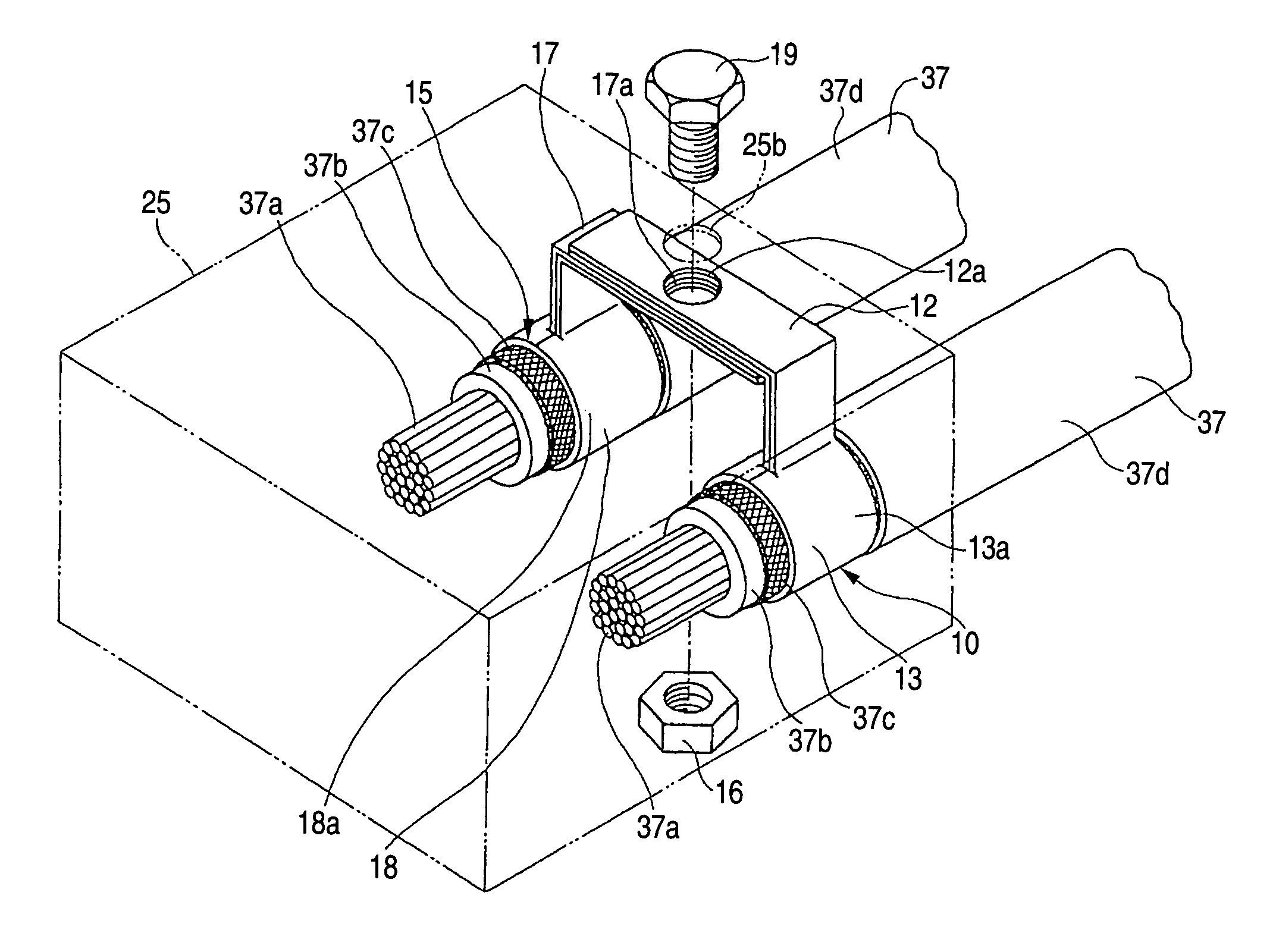
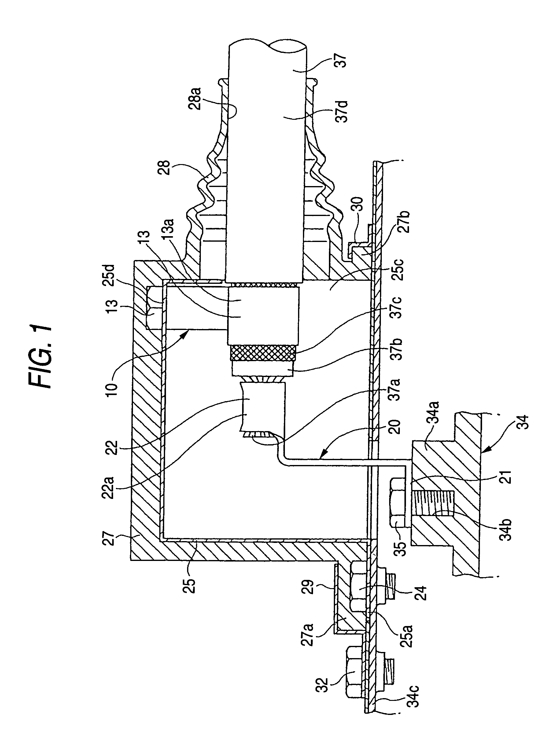
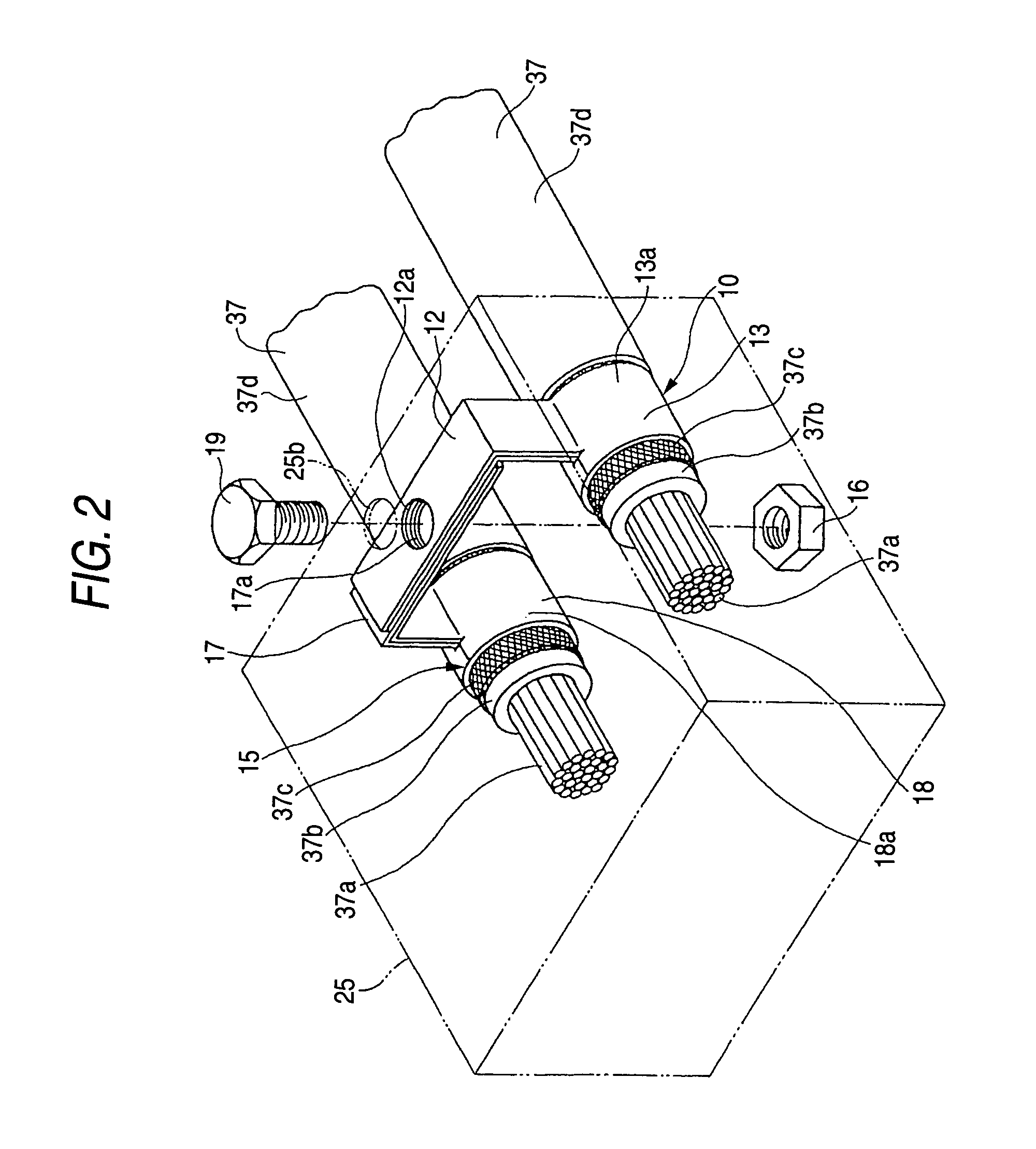
[0042]FIGS. 1 to 3 show a first embodiment of a shielded wire-connecting structure of the invention, and FIG. 4 shows a modified example thereof, and FIG. 5 shows a second embodiment.

[0043]Adverse effects of electromagnetic waves on an actuator (equipment), such as a motor, an inverter, an electronic control unit and a fuel injection device, mounted on an electric car, have now been at such a level that these effects can not be ignored. The shielded wire-connecting structure of the invention is designed to protect such an actuator from electromagnetic interference, that is, mainly from high-frequency electric and magnetic fields, to prevent a malfunction, thereby maintaining a safe travel of the car for a long period of time.

[0044]In the shielded wire-connecting structure of this embodiment, this connecting structure can be formed into a compact design, and besides the...


PUM


Abstract

In a shielded wire-connecting structure, a braided wire 37c of a shielded wire 37 is connected for grounding purposes to a shield shell 25 via a joint terminal 10, 15 which includes a wire connection portion 13 formed at one end thereof so as to be connected to the braided wire 37c, and a terminal mounting portion formed at the other end thereof so as to be connected to the shield shell 25. A passage hole for the passage of a fastening bolt 19 therethrough is formed through the terminal mounting portion, and the terminal mounting portions of a plurality of the joint terminals 10 and 15 are superposed together, with the passage holes communicating with each other, and are fastened together to the shield shell 25 by the fastening bolt 19 passing through the passage holes. A retaining step portion is formed at one of the terminal mounting portions which are to be superposed together, and an engagement step portion for engagement with the retaining step portion is formed at the other terminal mounting portion.

Description

BACKGROUND OF THE INVENTION[0001]1. Field of the Invention[0002]This invention relates to a shielded wire-connecting structure which is used in an electric car or the like, and causes electromagnetic waves, transmitting along a shielded wire, to escape to the exterior, and also to block electromagnetic waves from the exterior so as to eliminate adverse effects of such electromagnetic waves on an equipment.[0003]2. Related Art[0004]Many equipments, such as a motor, are mounted on a vehicle (serving as a mobile structure) such as an automobile, and adverse effects of electromagnetic waves, generated from these equipments and wires, have now been at such a level that these effects can not be ignored. Particularly, adverse effects of electromagnetic waves, generated from large-current / high-voltage equipments, have become a problem. Therefore, the equipments and wires have been protected from electromagnetic interference by the use of a suitable method such as an electromagnetic shieldin...

Claims


Application Information

Patent Timeline
Patent Type & Authority Patents(United States)
IPC IPC(8): H01R9/05H01R13/648H01R4/18H01R4/64H01R4/66H01R13/52
CPCH01R4/66H01R4/646H01R4/64H01R4/183H01R9/0518
Inventor MATSUI, TSUYOSHIADACHI, HIDEOMI
Owner YAZAKI CORP
Why Eureka
Try Eureka