Mattress for movable bed

Inactive Publication Date: 2006-06-08
SANYO ELECTRIC CO LTD
View PDF11 Cites 30 Cited by
  • Summary
  • Abstract
  • Description
  • Claims
  • Application Information

AI Technical Summary

Benefits of technology

[0007] Here, the fixture may be detachable from the platform. This structure is desirable since it facilitates the mattress replacement and the maintenance of the adjustable bed.
[0008] The fixture may be disposed, on the sur

Problems solved by technology

However, when such an adjustable bed operates, it is sometimes the case that a mattress laid on the bed is displaced, and thereby the care recipient on the mattress may be shifted from

Method used


Image

  • Mattress for movable bed
  • Mattress for movable bed
  • Mattress for movable bed

Examples


first embodiment

1. FIRST EMBODIMENT

[0022] 1.1 Structure of Adjustable Bed

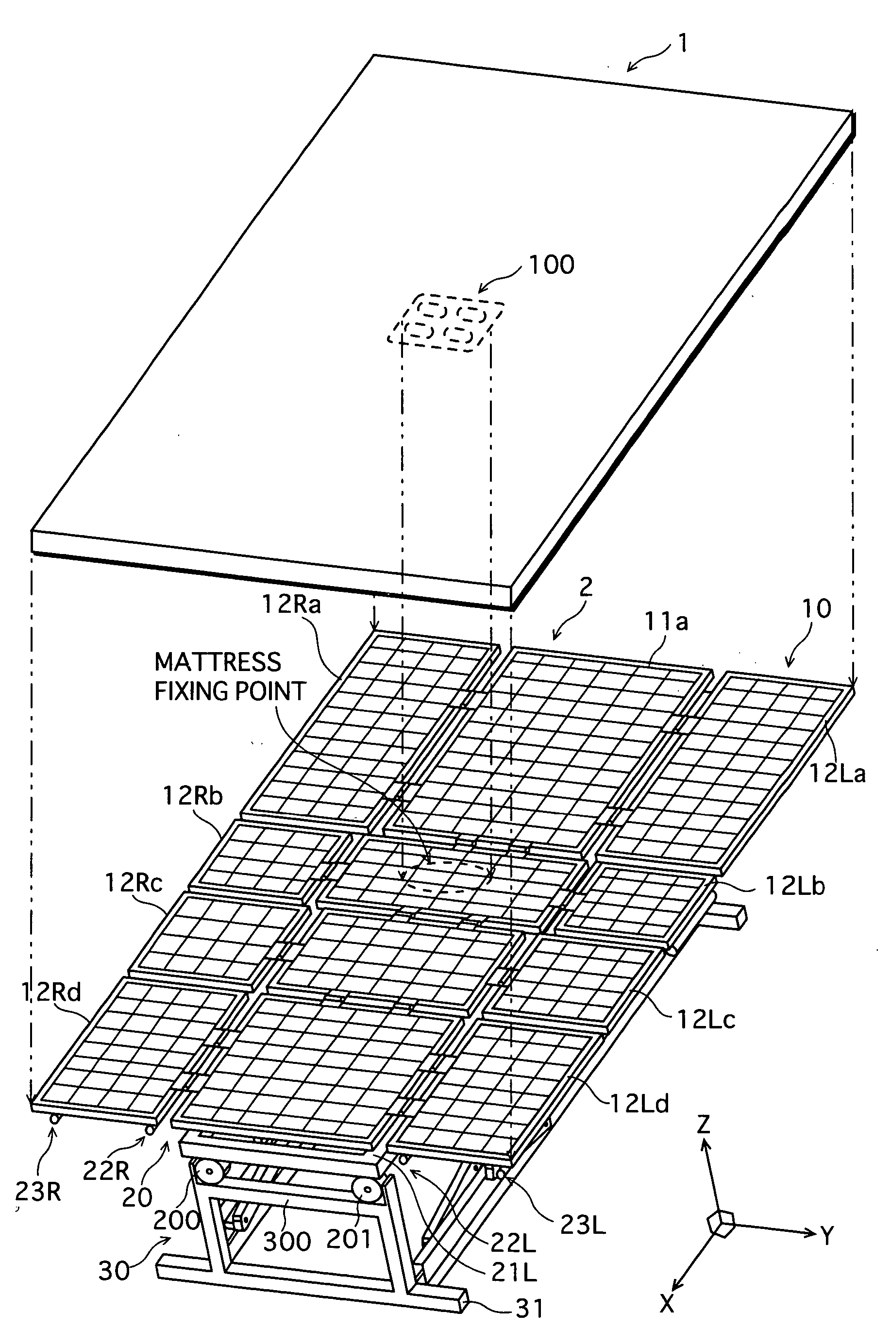
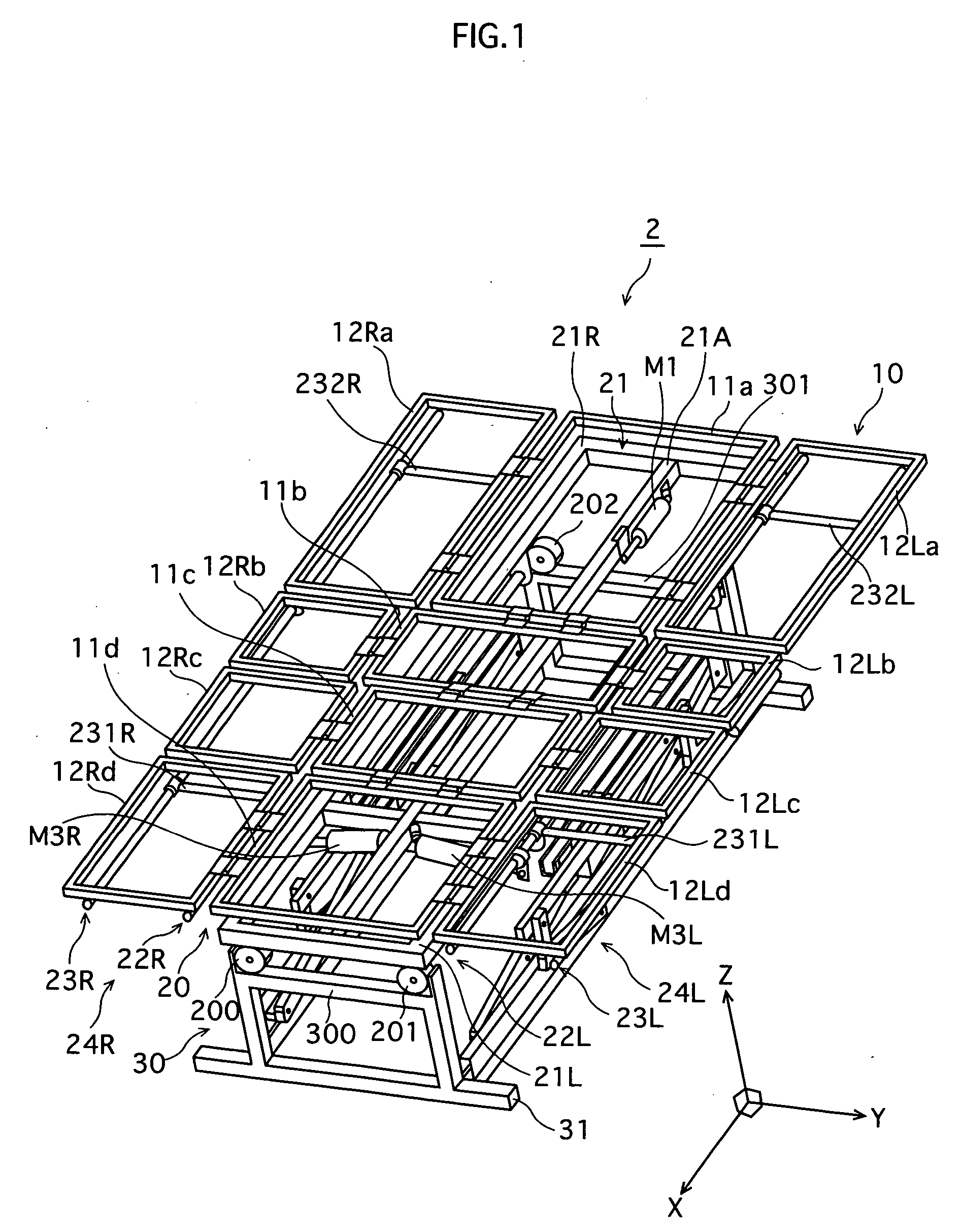
[0023]FIG. 1 is a perspective view illustrating a structure of an adjustable bed 2 according to a first embodiment of the present invention.

[0024] The adjustable bed 2 is constituted such that a bed frame 10 is disposed on an adjustable stage 20 placed on a fixed stage 30.

[0025] The bed frame 10 includes a coupled platform 11a-11d, which is formed by dividing a surface part (i.e. upper surface of the bed) into four sections corresponding to the back, hip, upper-leg, and lower-leg regions of a care recipient's body lying on the bed, and coupling these sections together so as to be freely adjustable. In the coupled platform 11a-11d, an upper-body member 11a, a lower-back member 11b, an upper-leg member 11c, and a lower-leg member 11d are each coupled in the given order.

[0026] The lower-back member 11b is fixed directly onto the adjustable stage 20 by welding, for example, thus preventing the bed frame 10 from being disengage...


PUM


Abstract

A mattress for a movable bed, laid on a floor portion of the movable bed whose bed face is deformable. A fixing element that is the floor portion is provided on a mattress surface opposite the floor portion. The movable bed may be constructed such that meshes are formed on a surface of the floor portion, and that the fixing element is fitted in gaps of the meshes to fix the mattress.

Description

TECHNICAL FIELD [0001] The present invention relates to a mattress designed to be laid on an adjustable bed used for nursing care. BACKGROUND ART [0002] In order to prevent the occurrence of decubitus ulcers, more commonly known as bedsores, adjustable beds used as turning beds and the like operate to assist postural change of care recipients. The postural change is generally achieved by inclining a part, or the entire mattress of the beds on which care recipients are lying so as to turn the care recipients in the direction of inclination (refer to Japanese Laid-Open Patent Application Publication No. H06-14824). The majority of these types of beds employ a mechanism that tilts the mattress surface from a flat position across the width direction of the mattress in order to assist the postural change. [0003] However, when such an adjustable bed operates, it is sometimes the case that a mattress laid on the bed is displaced, and thereby the care recipient on the mattress may be shifte...

Claims


Application Information

Patent Timeline
IPC IPC(8): A47C31/00A47C20/10A47C20/04A47C27/00A61G7/00A61G7/008A61G7/012A61G7/015A61G7/05A61G7/10
CPCA61G7/008A61G7/05A61G7/015A61G7/012A61G7/002
Inventor KAWAKAMI, HIDEOMORIKAWA, MASASHI
Owner SANYO ELECTRIC CO LTD
Why Eureka
Try Eureka