Back EMF measurement to overcome the effects of motor temperature change

a technology of back emf and temperature change, which is applied in the direction of instruments, mechanical equipment, centrifuges, etc., can solve the problem of difficulty in accurately estimating the energy added to the rotor

Inactive Publication Date: 2006-06-08
THERMO FISHER SCI ASHEVILLE
View PDF4 Cites 15 Cited by
  • Summary
  • Abstract
  • Description
  • Claims
  • Application Information

AI Technical Summary

Benefits of technology

[0006] The foregoing needs are met, to a great extent, by the present invention, wherein in one aspect an apparatus is provided that in some embodiments utilizes a back EMF measurement to overcome the effects of motor temperature change.

Problems solved by technology

This makes it difficult to accurately estimate the energy added to the rotor.

Method used


Image

  • Back EMF measurement to overcome the effects of motor temperature change
  • Back EMF measurement to overcome the effects of motor temperature change
  • Back EMF measurement to overcome the effects of motor temperature change

Examples


Embodiment Construction

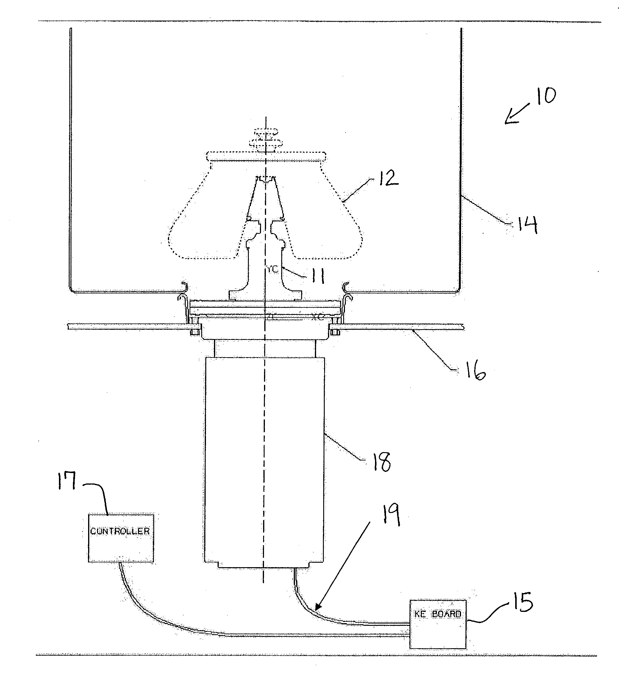
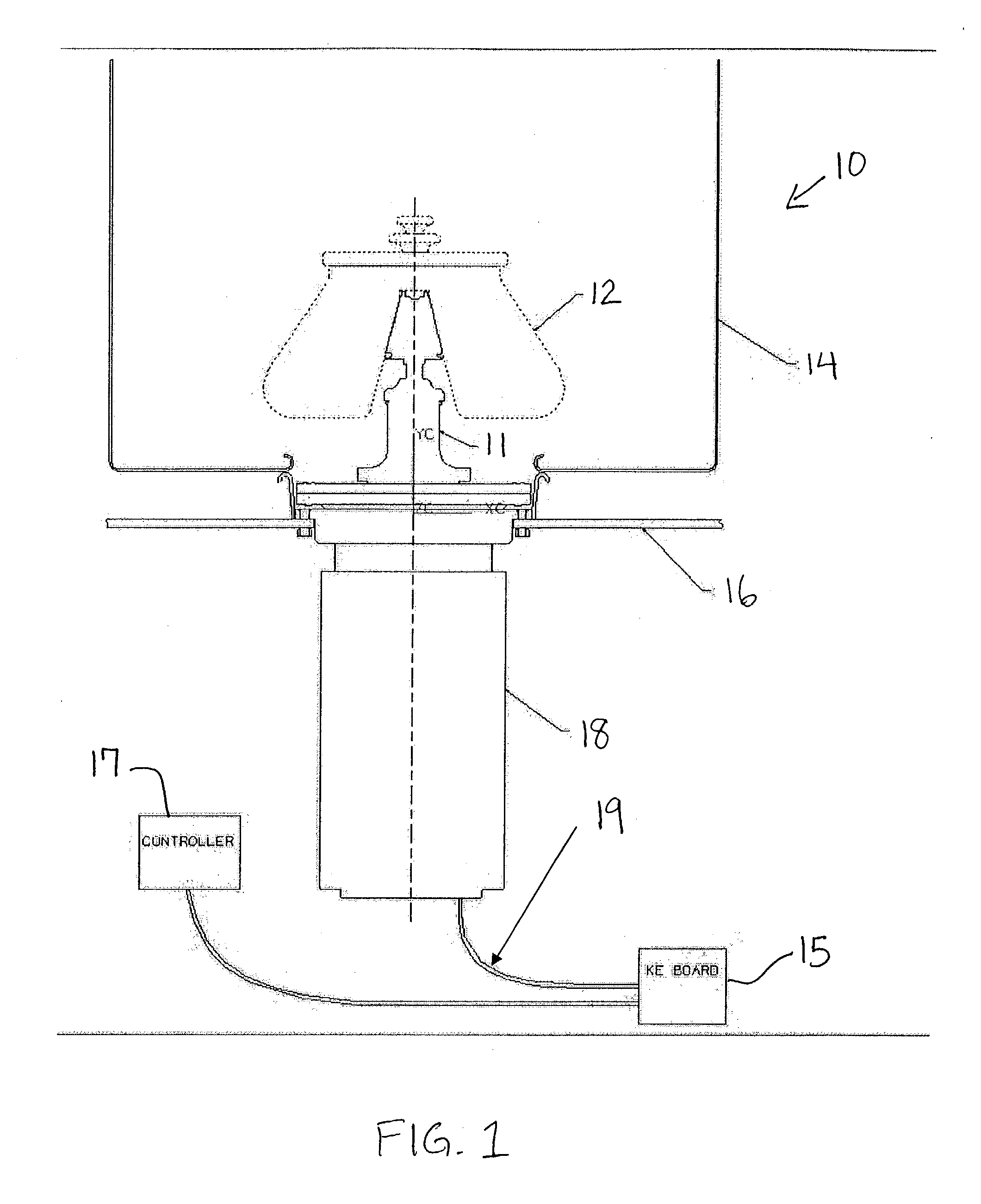
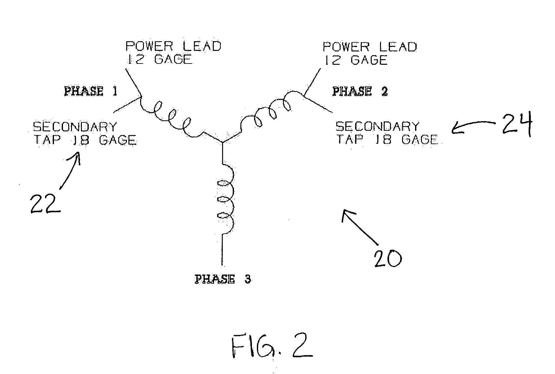
[0015] Referring to FIG. 1, a preferred embodiment of the invention provides a centrifuge 10 having a gyro / motor rotor 11, a centrifuge rotor 12, an axis of rotation 13, an evaporator 14, a Ke Board / Circuit 15, a centrifuge housing 16, a controller 17, a motor 18 and phase pair motor taps 19.

[0016] As the temperature of the motor 18 increases, its back EMF coefficient (Ke) decreases in a known manner determined by its magnet material temperature coefficient. The Ke value is defined as the amount of voltage that a freely rotating motor will generate per 1000 revolutions per minute (RPM). It is not easy to directly measure the temperature of the rotating magnetic material and without knowing the magnet temperature, the change in Ke cannot be directly calculated. By momentarily removing the drive power from the motor 18 and allowing the motor 18 to coast, the back EMF and RPM can be measured simultaneously and the Ke of the motor 18 can readily be calculated.

[0017] Because the mass m...


PUM


Abstract

Methods and apparatus for a centrifuge motor, which are particularly suited for measuring and calculating the back EMF coefficient (Ke) of the motor and motor temperature.

Description

PRIORITY [0001] This application claims priority to the provisional U.S. patent application entitled BACK EMF MEASUREMENT TO OVERCOME THE EFFECTS OF MOTOR TEMPERATURE CHANGE, filed May 21, 2002, having a Ser. No. 60 / 381,824, the disclosure of which is hereby incorporated by reference.FIELD OF THE INVENTION [0002] The present invention relates generally to back EMF measurements as related to motor temperature. The invention specifically relates to brushless DC or permanent magnet motors, but can be used to measure the change in a motor constant on any type of motor affected by a rise in motor temperature. More particularly, the present invention relates to centrifuge motors and the measurement of the back EMF coefficient, or (Ke, volts / rpm) to overcome the effects of motor temperature changes. BACKGROUND OF THE INVENTION [0003] A centrifuge instrument is a device by which liquid samples may be subjected to centrifugal forces. The sample is carried within a member known as a centrifug...

Claims


Application Information

Patent Timeline
Patent Type & Authority Applications(United States)
IPC IPC(8): G01C19/54
CPCB04B9/10H02P6/182Y10T74/1229H02P29/0066H02P23/14H02P29/662
Inventor SCHNEIDER, HARVEYCARSON, DAVID MICHAEL
Owner THERMO FISHER SCI ASHEVILLE
Why Eureka
Try Eureka