Geared transmission apparatus

a transmission device and gear technology, applied in the direction of gearing, toothed gearings, agriculture, etc., can solve the problems of shortened service increased angle or tooth width, and reduced number of teeth, so as to reduce backlash, facilitate adjustment, and prolong the useful life of gears and bearings

Inactive Publication Date: 2006-06-08
JAPAN SERVO CO LTD
View PDF4 Cites 11 Cited by
  • Summary
  • Abstract
  • Description
  • Claims
  • Application Information

AI Technical Summary

Benefits of technology

[0005] An object of the present invention, attempted in view of the shortcomings noted above, is to facilitate adjustment of and reduce backlash in geared transmission apparatuses using conical gears. The invention is also intended to extend the useful lives of gears and bearings in geared transmission apparatuses.

Problems solved by technology

This trouble occurs where the cone angle or the tooth width is greater, or the number of teeth is smaller.
As a result, the service lives of the gears and bearings are shortened, and the noise and vibration of the geared transmission apparatus increase.

Method used


Image

  • Geared transmission apparatus
  • Geared transmission apparatus
  • Geared transmission apparatus

Examples


Embodiment Construction

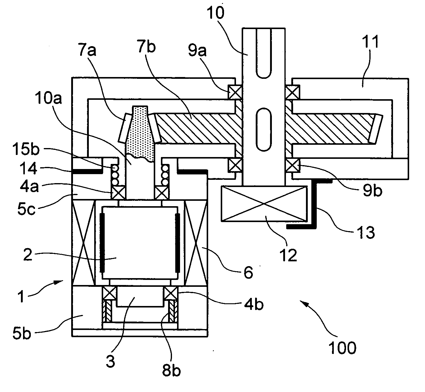
[0013] A few geared transmission apparatuses, which are preferred embodiments according to the present invention, will be described below with reference to the accompanying drawings. FIG. 1 shows a vertical section of a geared transmission apparatus 100. What is illustrated in this drawing is a small geared transmission apparatus 100 for use in an actuator for driving a robot arm or the like.

[0014] At the center of a driving motor 1, there are a rotor core 2 and a pinion shaft 3 formed integrally with this rotor core 2 and long extending toward one end. A stator core 6 is arranged around the rotor core 2 at some spacing from this rotor core 2. Motor housings 5a and 5b are fitted to the two ends of the stator core 6 in the axial direction. On the inner circumferential sides of the motor housings 5a and 5b, there are held pinion bearings 4a and 4b which rotatably support the pinion shaft 3. The driving motor 1 is a motor for control use, such as a stepping motor for example.

[0015] A...


PUM


Abstract

In a parallel shaft-type of conical-geared transmission apparatus, a conical pinion is fitted to a first rotation shaft, and a second rotation shaft is arranged in parallel to this first rotation shaft. A conical wheel meshing with the conical pinion is fitted to the second rotation shaft. The pinion and the wheel are substantially equal in cone angle. A supporting device supports the first rotation shaft to be movable in the axial direction. A pressing device applies thrust in the axial direction of the first rotation shaft. A load bearing body to bear the thrust applied by the pressing device and to allow the first rotation shaft to be displaced in the radial direction is provided at an end of the first rotation shaft.

Description

CROSS REFERENCE TO RELATED APPLICATION [0001] The present application claims priority from Japanese application JP-A-2004-307565 filed on Oct. 22, 2004, the content of which is hereby incorporated by reference into this application. BACKGROUND OF THE INVENTION [0002] The present invention relates to a geared transmission apparatus and more particularly to a geared transmission apparatus suitable for use in an actuator. An example of conventional geared transmission apparatus using a pair of conical gears is described in JP-A-6-257660. In the geared transmission apparatus described in this patent publication, the pitch surface of at least one of the gears is cylindrical, and the tooth curve is inclined by the cone angle relative to the axis of rotation, and the module of teeth does not vary along this tooth curve. The addendum modification coefficient of the geared transmission apparatus and the external dimension of the gears vary linearly. Further, there is provided a pressing mech...

Claims


Application Information

Patent Timeline
Patent Type & Authority Applications(United States)
IPC IPC(8): F16H1/14F16H1/06F16H57/021F16H57/12
CPCF16H1/06Y10T74/19688F16H2057/128F16H57/12A01G17/14
Inventor OHNO, KOUSAKUSHOJI, KENSUKE
Owner JAPAN SERVO CO LTD
Why Eureka
Try Eureka