Pipe running tool having internal gripper

a running tool and gripper technology, applied in the direction of drilling pipes, drilling casings, borehole/well accessories, etc., can solve the problems of cumbersome and relatively inefficient methods, high cost, and high labor intensity of methods

Inactive Publication Date: 2006-06-08
VARCO I P INC
View PDF52 Cites 43 Cited by
  • Summary
  • Abstract
  • Description
  • Claims
  • Application Information

AI Technical Summary

Problems solved by technology

The conventional manner in which plural casing segments are coupled together to form a casing string is a labor-intensive method involving the use of a “stabber” and casing tongs.
While such a method is effective, it is cumbersome and relatively inefficient because the procedure is done manually.
Thus, such a method is relatively labor-intensive and therefore costly.
Furthermore, using casing tongs requires the setting up of scaffolding or other like structures, and is therefore inefficient.

Method used


Image

  • Pipe running tool having internal gripper
  • Pipe running tool having internal gripper
  • Pipe running tool having internal gripper

Examples


Embodiment Construction

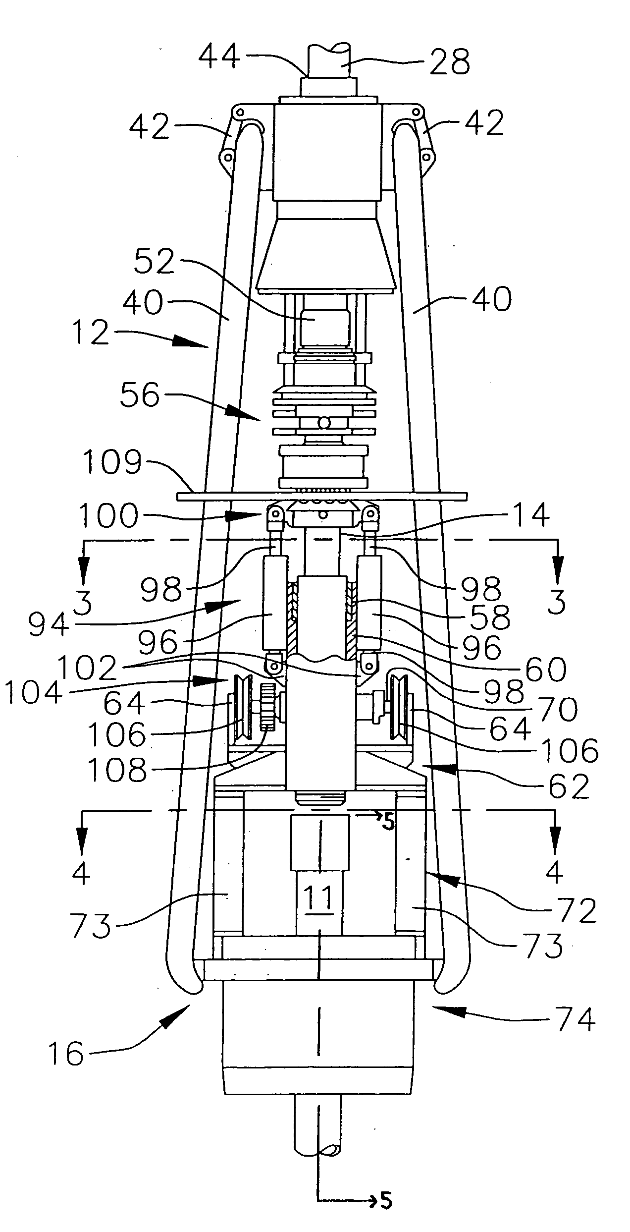
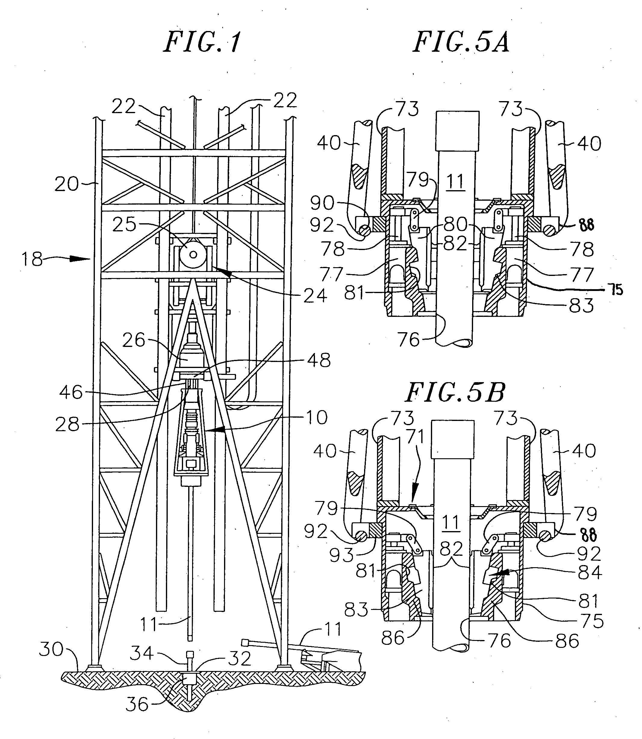
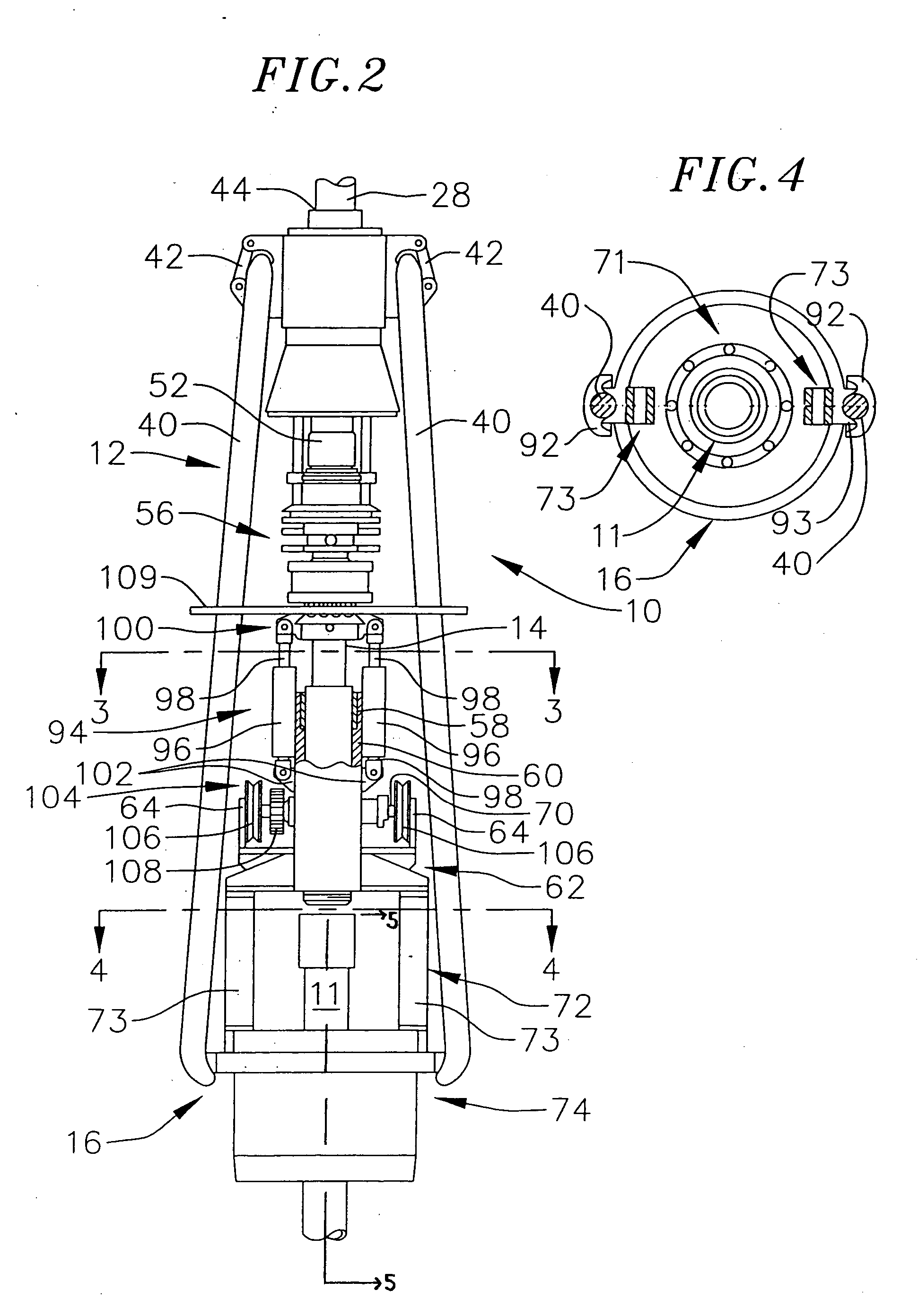
[0023] As shown in FIGS. 1-10, the present invention is directed to a pipe running tool for use in drilling systems and the like to threadingly connect pipe segments to pipe strings (as used hereinafter, the term pipe segment shall be understood to refer to casing segments and / or drill segments, while the term pipe string shall be understood to refer to casing strings and / or drill strings.)

[0024] The pipe running tool according to the present invention engages a pipe segment and is further coupled to an existing top drive assembly, such that a rotation of the top drive assembly imparts a torque on the pipe segment during a threading operation between the pipe segment and a pipe string. In one embodiment, the pipe running tool includes a load compensator which controls the load that the threads of the pipe segment apply to the threads of the pipe string during a threading operation.

[0025] In one embodiment, the pipe running tool includes a spider elevator for engaging an external d...


PUM


Abstract

A system for coupling a pipe segment to a pipe string is provided that includes a top drive assembly having an output shaft; and a pipe running tool coupled to the top drive assembly and rotatable by the output shaft of the top drive assembly. The pipe running tool includes an internal gripper for insertion within an internal diameter of the pipe segment and a tapered slip cone section, which slidably receives corresponding tapered surfaces of a plurality of slips, such that a vertical force on the slips causes the slips to move radially outwardly into gripping engagement with the internal diameter of the pipe segment, and wherein the vertical force applied to the slips is sufficient to allow the gripping engagement of the slips with the internal diameter of the pipe segment to transmit a torque from the top drive output shaft to the pipe segment.

Description

CROSS-REFERENCE TO RELATED APPLICATION(S) [0001] This application is a continuation-in-part of U.S. patent application Ser. No. 11 / 040,453, filed on Jan. 20, 2005, which is a continuation of U.S. patent application Ser. No. 10 / 189,355, filed on Jul. 3, 2002, which is a continuation of U.S. patent application Ser. No. 09 / 518,122, filed Mar. 3, 2000, issued as U.S. Pat. No. 6,443,241, which claims priority under 35 U.S.C. § 119(e) to U.S. Provisional Patent Application No. 60 / 122,915, filed on Mar. 5, 1999.BACKGROUND OF THE INVENTION [0002] 1. Field of the Invention [0003] This invention relates to well drilling operations and, more particularly, to a device for assisting in the assembly of pipe strings, such as casing strings, drill strings and the like. [0004] 2. Description of the Related Art [0005] The drilling of oil wells involves assembling drill strings and casing strings, each of which comprises a plurality of elongated, heavy pipe segments extending downwardly from an oil dr...

Claims


Application Information

Patent Timeline
Patent Type & Authority Applications(United States)
IPC IPC(8): E21B19/18
CPCE21B19/07E21B31/20
Inventor JUHASZ, DANIELBOYADJIEFF, GEORGEEIDEM, BRIAN L.RIJZINGEN, HANS VANKAMPHORST, HERMAN M.BOTTGER, HANS JOACHIM DIETRICHWECHEM, GUSTAAF LOUIS VANMASON, DAVIDKRIJNEN, ANTON
Owner VARCO I P INC
Why Eureka
Try Eureka