Circuit for generating ternary signal
a ternary signal and circuit technology, applied in the direction of logic circuits using specific components, pulse generators, pulse techniques, etc., can solve the problems of complex circuits, disadvantages of miniaturization and cost reduction of the entire device, and achieve cost reduction
- Summary
- Abstract
- Description
- Claims
- Application Information
AI Technical Summary
Benefits of technology
Problems solved by technology
Method used
Image
Examples
first preferred embodiment
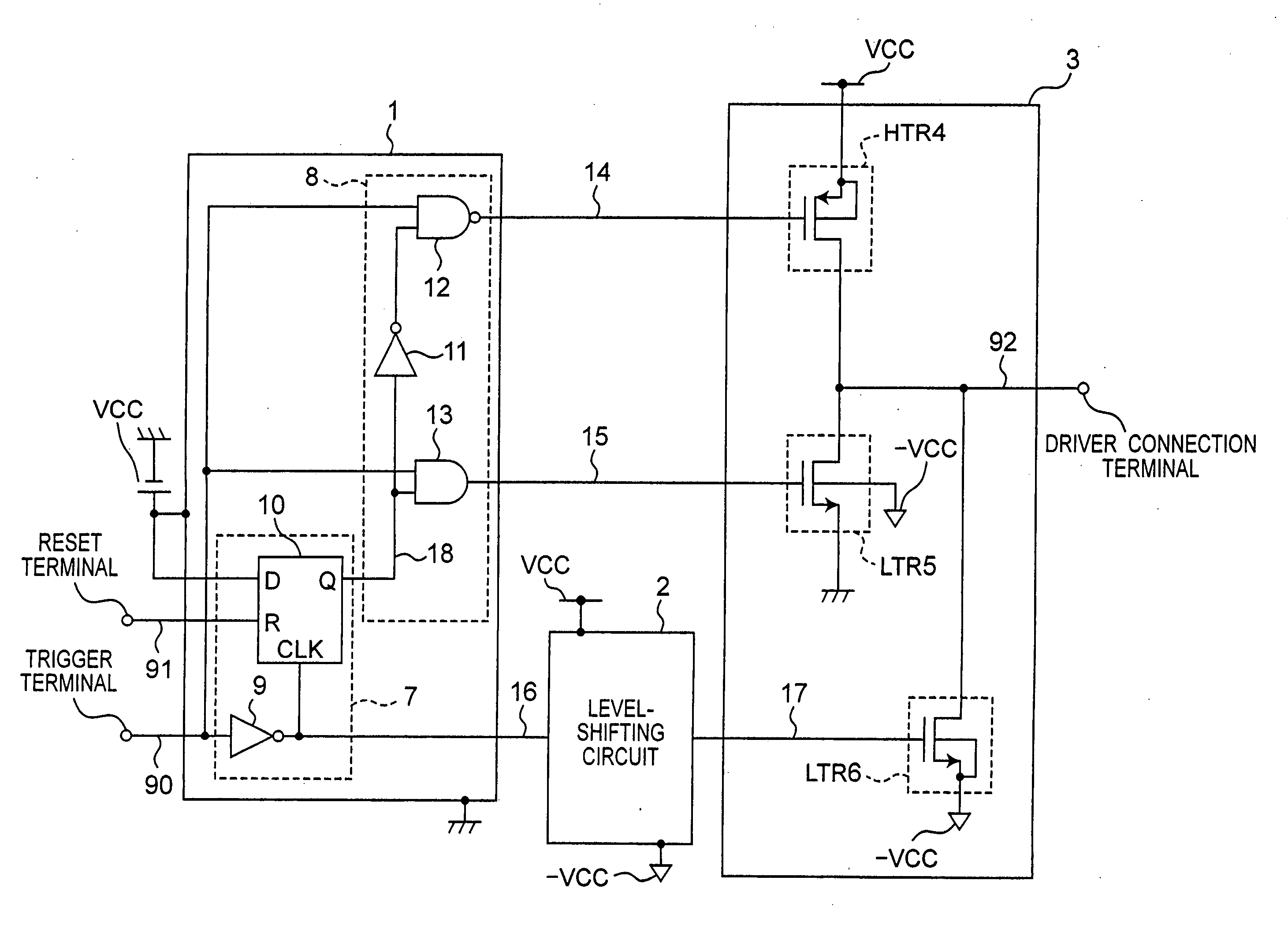
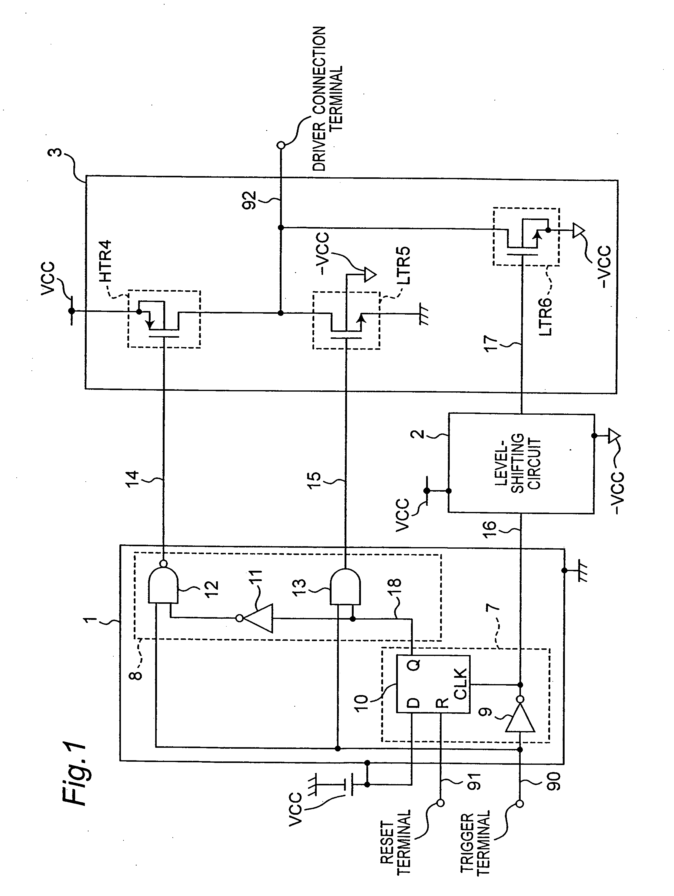
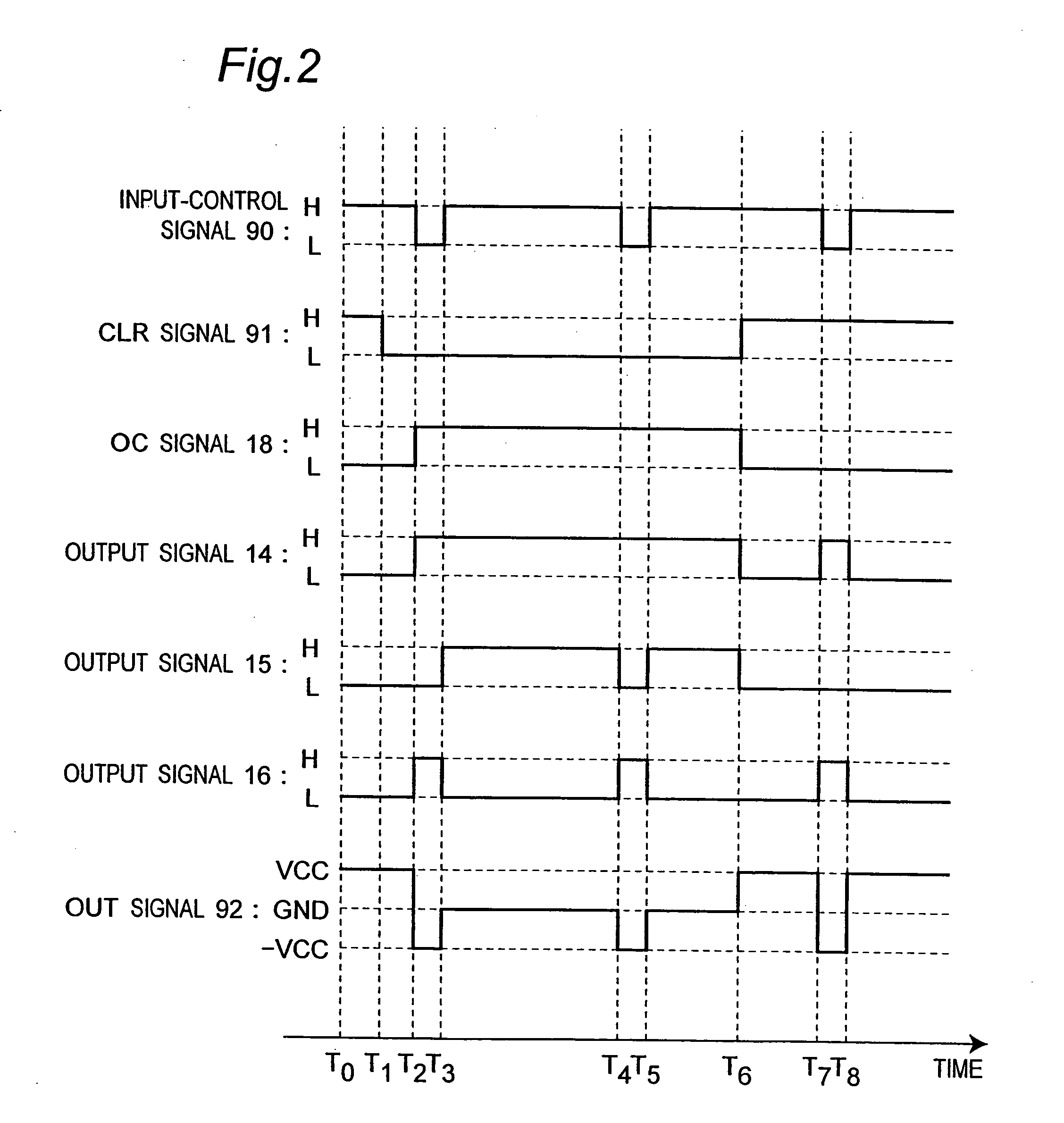
[0051] Referring to FIGS. 1 and 2, a circuit for generating a ternary signal in accordance with a first preferred embodiment of the present invention will be described. FIG. 1 is a circuit diagram showing a configuration of the circuit for generating a ternary signal in accordance with this first preferred embodiment of the present invention. In FIG. 1, the circuit for generating a ternary signal includes a sequential circuit 1, a level-shifting circuit 2, and a ternary output generating circuit 3.
[0052] The sequential circuit 1 includes an edge detecting circuit 7 and a switching circuit 8. The ternary output generating circuit 3 includes a high-potential-side P-channel transistor 4 (hereinafter, referred to as an HTR4), a low-potential-side N-channel transistor 5 (hereinafter, referred to as an LTR5), and a low-potential-side N-channel transistor 6 (hereinafter, referred to as an LTR6).
[0053] The edge detecting circuit 7 of the sequential circuit 1 is composed by a D-type flip-f...
second preferred embodiment
[0085] Referring to FIGS. 3 and 4, a circuit for generating a ternary signal in accordance with a second preferred embodiment of the present invention will be described. FIG. 3 is a circuit diagram showing a configuration of the circuit for generating a ternary signal in accordance with this second preferred embodiment of the present invention. In FIG. 3, the circuit for generating a ternary signal in accordance with this second preferred embodiment of the present invention is different from that of the first preferred embodiment of the present invention shown in FIG. 1 in that a level-shifting circuit 25 is provided instead of the level-shifting circuit 2, a ternary output generating circuit 27 is provided instead of the ternary output generating circuit 3, and a level-shifting circuit 26 is added.
[0086] In the circuit for generating a ternary signal of the prior art shown in FIG. 7 and in the circuit for generating a ternary signal in accordance with the first preferred embodimen...
third preferred embodiment
[0108] Referring to FIGS. 5 and 6, a circuit for generating a ternary signal in accordance with a third preferred embodiment of the present invention will be described. FIG. 5 is a circuit diagram showing a configuration of the circuit for generating a ternary signal in accordance with this third preferred embodiment of the present invention. In FIG. 5, the circuit for generating a ternary signal in accordance with this third preferred embodiment of the present invention is different from that of the first preferred embodiment of the present invention shown in FIG. 1 in that a sequential circuit 35 is provided instead of the sequential circuit 1, the level-shifting circuit 2 is removed, level-shifting circuit 40 and 41 are added, and a ternary output generating circuit 42 is provided instead of the ternary output generating circuit 3.
[0109] In the circuit for generating a ternary signal of the prior art shown in FIG. 7 and in the circuit for generating a ternary signal in accordanc...
PUM
 Abstract
Description
Claims
Application Information
 - R&D
- Intellectual Property
- Life Sciences
- Materials
- Tech Scout
- Unparalleled Data Quality
- Higher Quality Content
- 60% Fewer Hallucinations
Browse by: Latest US Patents, China's latest patents, Technical Efficacy Thesaurus, Application Domain, Technology Topic, Popular Technical Reports.
© 2025 PatSnap. All rights reserved.Legal|Privacy policy|Modern Slavery Act Transparency Statement|Sitemap|About US| Contact US: help@patsnap.com


