
Flat fluorescent lamp and liquid crystal display apparatus having the same

a fluorescent lamp and liquid crystal display technology, applied in the field of flat fluorescent lamps, can solve the problems of deterioration of optical characteristics, affecting the uniformity of luminance, and the need for a greater number of ccfls, so as to prevent processing failure, improve uniformity, and reduce the thickness of flat fluorescent lamps.

Inactive Publication Date: 2006-06-08
SAMSUNG ELECTRONICS CO LTD
View PDF8 Cites 2 Cited by
  • Summary
  • Abstract
  • Description
  • Claims
  • Application Information

AI Technical Summary

Benefits of technology

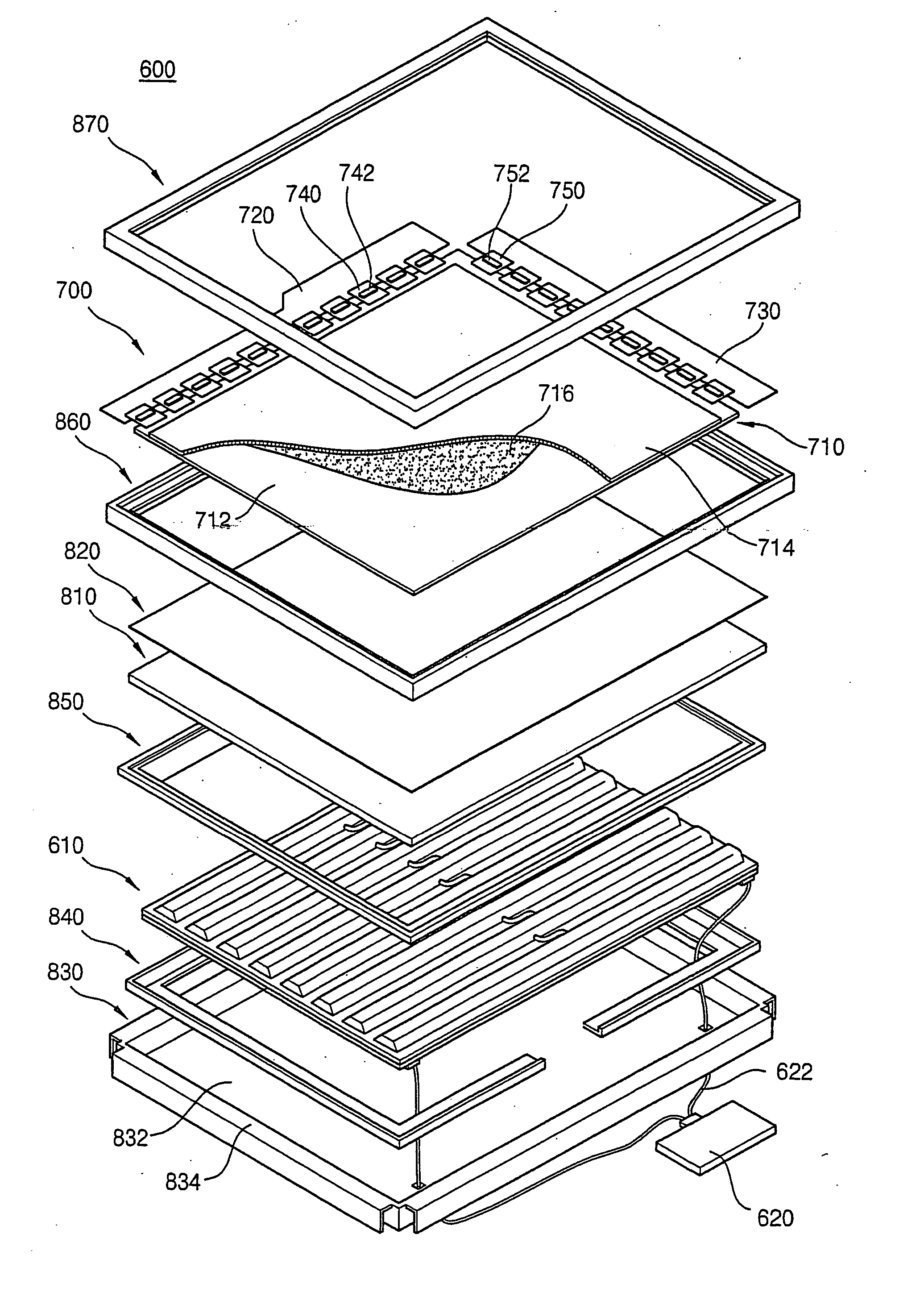
The present invention provides a flat fluorescent lamp with improved mounting of a getter and an LCD apparatus using the flat fluorescent lamp. The flat fluorescent lamp includes a first substrate and a second substrate combined to form a discharge space between them. The getter is securely attached to the first substrate with a wing portion and a bended portion. The flat fluorescent lamp does not require an exhaustion tube to mount the getter, which reduces its thickness and prevents processing failures. The getter is more stable and securely attached to the substrate due to the wing portion. The LCD apparatus includes the flat fluorescent lamp and a reflective layer, fluorescent layers, and an inverter for applying a discharge voltage to the lamp. The apparatus also includes a diffusing plate, an optical sheet, and a receiving container for the lamp. The technical effects of the invention include improved mounting of the getter, reduced thickness of the lamp, and stability of the getter attachment.

Problems solved by technology

However, recent trends in the industry to produce larger LCD apparatuses necessarily result in the need for a greater number of CCFLs.
As a consequence, manufacturing costs for the LCD apparatus is increased and optical characteristics, such as luminance uniformity characteristics are deteriorated.
However, although the exhaustion tube is removed from the lamp body, a residue of the exhaustion tube may remain, thereby increasing a thickness of the flat fluorescent lamp.
Moreover, the exhaustion tube may be broken during the manufacturing process of the flat fluorescent lamp, thereby decreasing productivity in its manufacture.

Method used


Image

  • Flat fluorescent lamp and liquid crystal display apparatus having the same
  • Flat fluorescent lamp and liquid crystal display apparatus having the same
  • Flat fluorescent lamp and liquid crystal display apparatus having the same

Examples


Embodiment Construction

[0029] Hereinafter, the exemplary embodiments of the present invention will be described in detail with reference to the accompanying drawings.

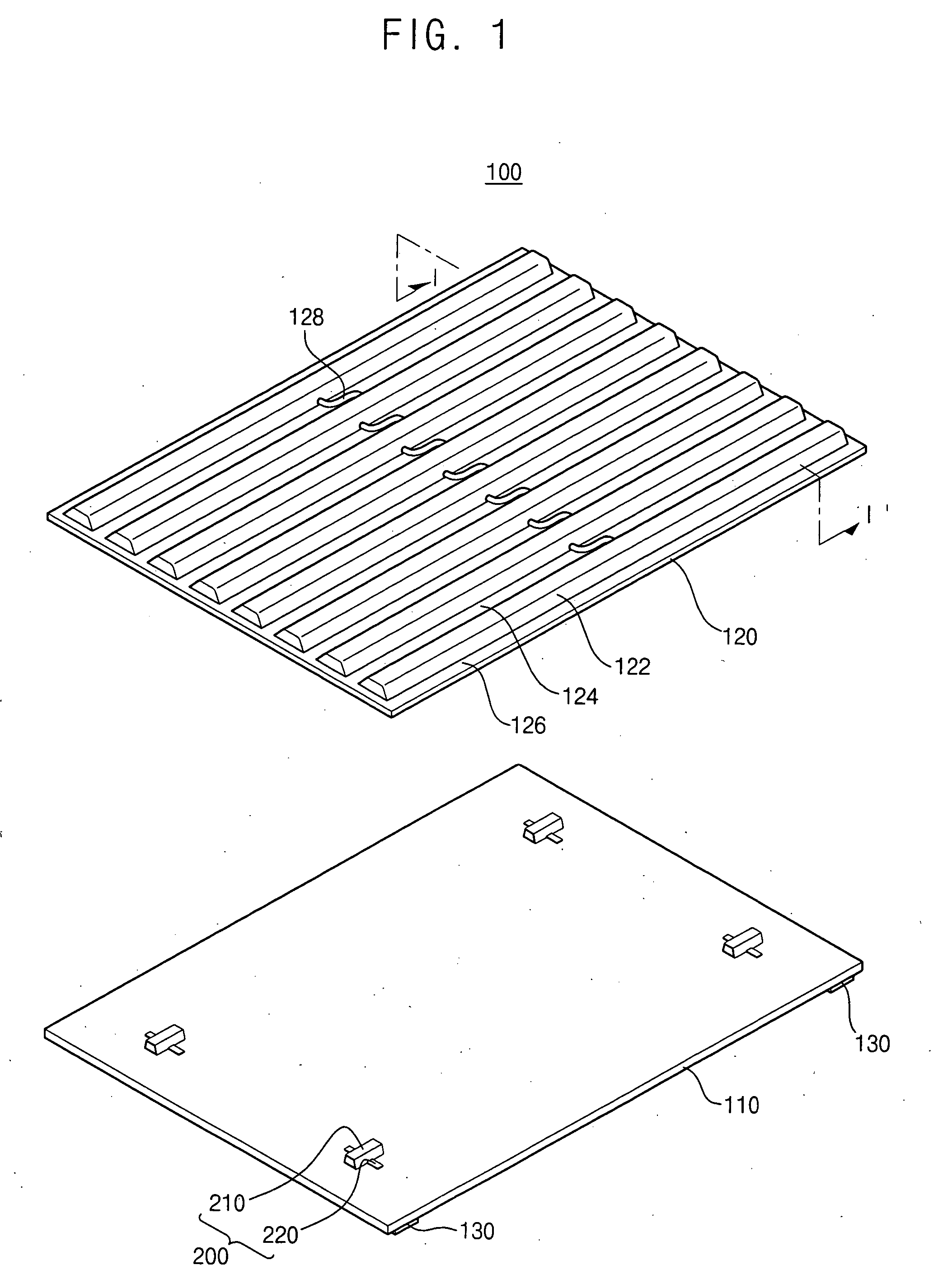
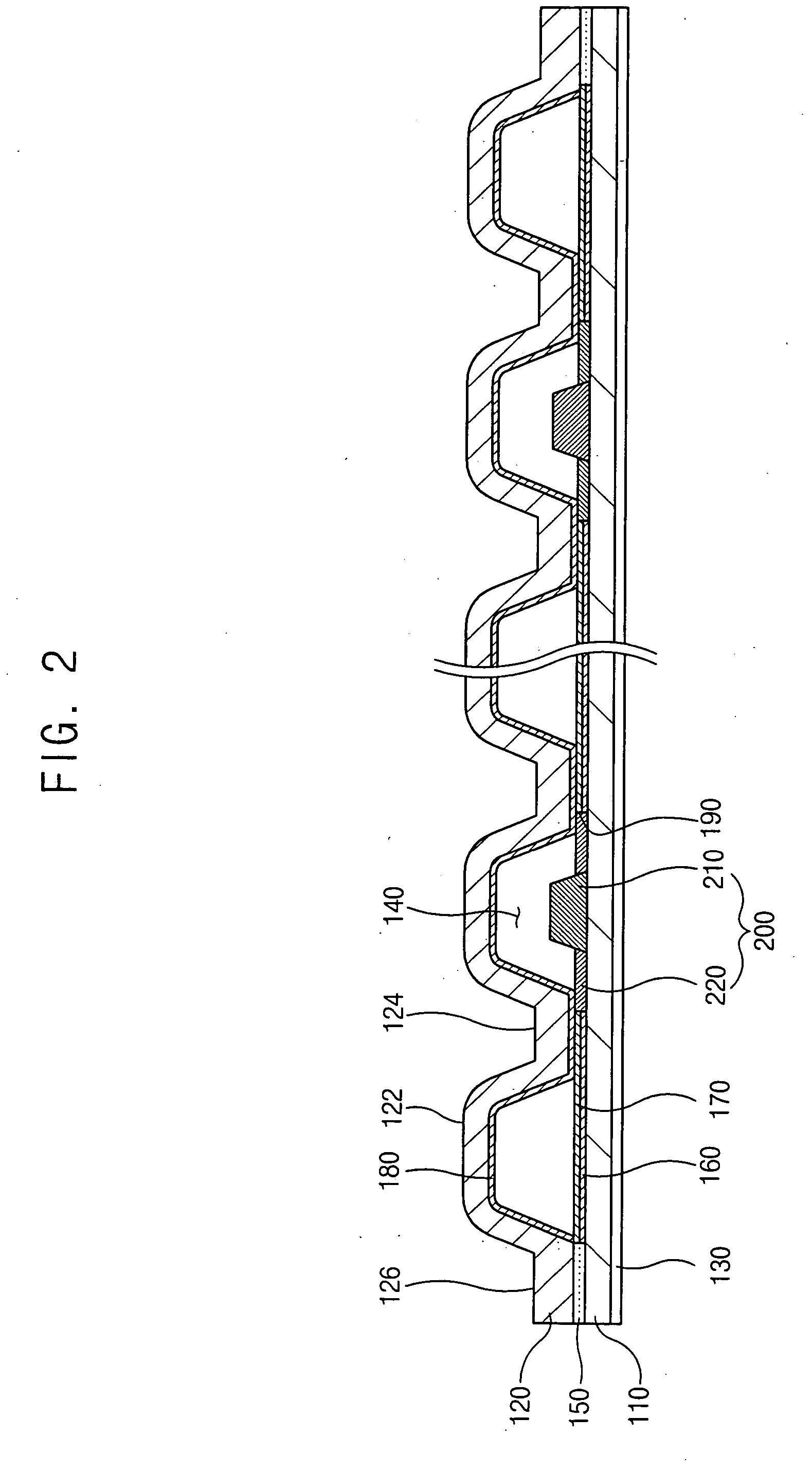
[0030]FIG. 1 is an exploded perspective view illustrating a flat fluorescent lamp in accordance with an exemplary embodiment of the present invention and FIG. 2 is a cross-sectional view illustrating an assembled structure of the flat fluorescent lamp of FIG.1 taken along line I-I′.

[0031] Referring to FIGS. 1 and 2, a flat fluorescent lamp 100 according to an exemplary embodiment of the present invention includes a first substrate 110, a second substrate 120 and a getter 200. The second substrate 120 is combined with the first substrate 110, and a plurality of discharge spaces is formed between the first and second substrates 110 and 120. The getter 200 is positioned in at least one of the discharge spaces, so that a mercury gas is provided into one of the discharge spaces 140 (FIG. 2) as will be described. As shown in FIGS. 1 and 2, the ge...


PUM

PropertyMeasurementUnit
pressureaaaaaaaaaa
pressureaaaaaaaaaa
thicknessaaaaaaaaaa

Abstract

A flat fluorescent lamp and liquid crystal display apparatus having the same is provided. The flat fluorescent lamp includes a first substrate and a second substrate combined with the first substrate to form a discharge space between the first and second substrates. The flat fluorescent lamp also includes a getter disposed in the discharge space. The getter includes a body portion and a wing portion for securing the body portion.

Description

[0001] The present application claims priority to Korean Patent Application No. 2004-91363 filed on Nov. 10, 2004, the contents of which are herein incorporated by reference in its entirety. BACKGROUND OF THE INVENTION [0002] 1. Field of the Invention [0003] The present invention relates generally to a flat fluorescent lamp for generating light for displaying images and a liquid crystal display apparatus having the flat fluorescent lamp. More particularly, the present invention relates to a flat fluorescent lamp comprising a getter configured for use without an exhaustion tube and a liquid crystal display apparatus having the flat fluorescent lamp. [0004] 2. Description of the Related Art [0005] Generally, a liquid crystal display (LCD) apparatus, one of flat display apparatuses, displays images by using liquid crystal. The LCD apparatus has many merits, for example, thin thickness, lightweight, low power consumption, low driving voltage, etc., making it ideal for use in a variety o...

Claims


Application Information

Patent Timeline
Patent Type & Authority Applications(United States)
IPC IPC(8): G02F1/1335
CPCB25H3/04Y10S206/806G02F1/1335
Inventor KIM, JOONG-HYUNLEE, SANG-YUHWANG, IN-SUN
Owner SAMSUNG ELECTRONICS CO LTD
Learn More