Aperture plate and related system and method

a technology of aperture plate and aperture plate, applied in the field of aperture plate, can solve the problems of creating visible image artifacts, bright spots in the image, visible artifacts in the viewed image, etc., and achieve the effect of reducing the cost and/or difficulty of manufacturing an imaging system

Active Publication Date: 2006-06-08
MICROVISION
View PDF7 Cites 20 Cited by
  • Summary
  • Abstract
  • Description
  • Claims
  • Application Information

AI Technical Summary

Benefits of technology

[0010] The aperture plate blocks at least a portion of electromagnetic energy, e.g., a light beam, from striking undesired portions of the reflector, and the plate surface deflects peripheral energy in one or more directions that are different from the direction or directions in which

Problems solved by technology

This is because the often poor-optical-quality perimeter of the mirror 34 and structure that supports the mirror (e.g., MEMS torsion arms) may scatter or otherwise reflect light from the periphery of the beam 13 (i.e., light that strikes beyond the boundary of the clear-optical-quality surface of the mirror) into the image, and thus create visible image artifacts.
But because light reflected from the mirror-support structures is not scanned, the eyes do not integrate this light over the area of the image.
Consequently, this reflected light may cause bright spots in the image.
Even a relatively small amount of this unwanted reflected light can cause a vi

Method used


Image

  • Aperture plate and related system and method
  • Aperture plate and related system and method
  • Aperture plate and related system and method

Examples


Embodiment Construction

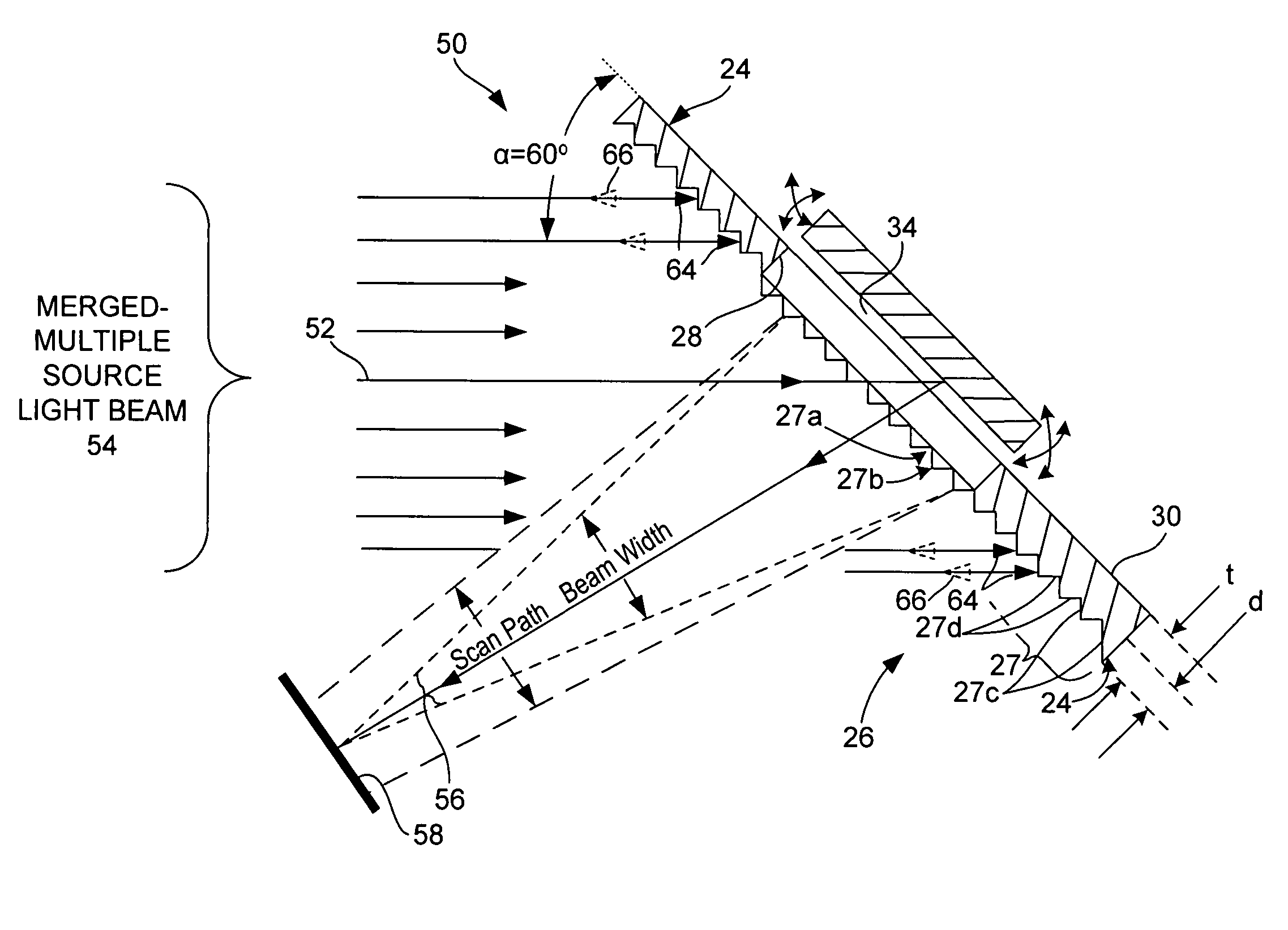
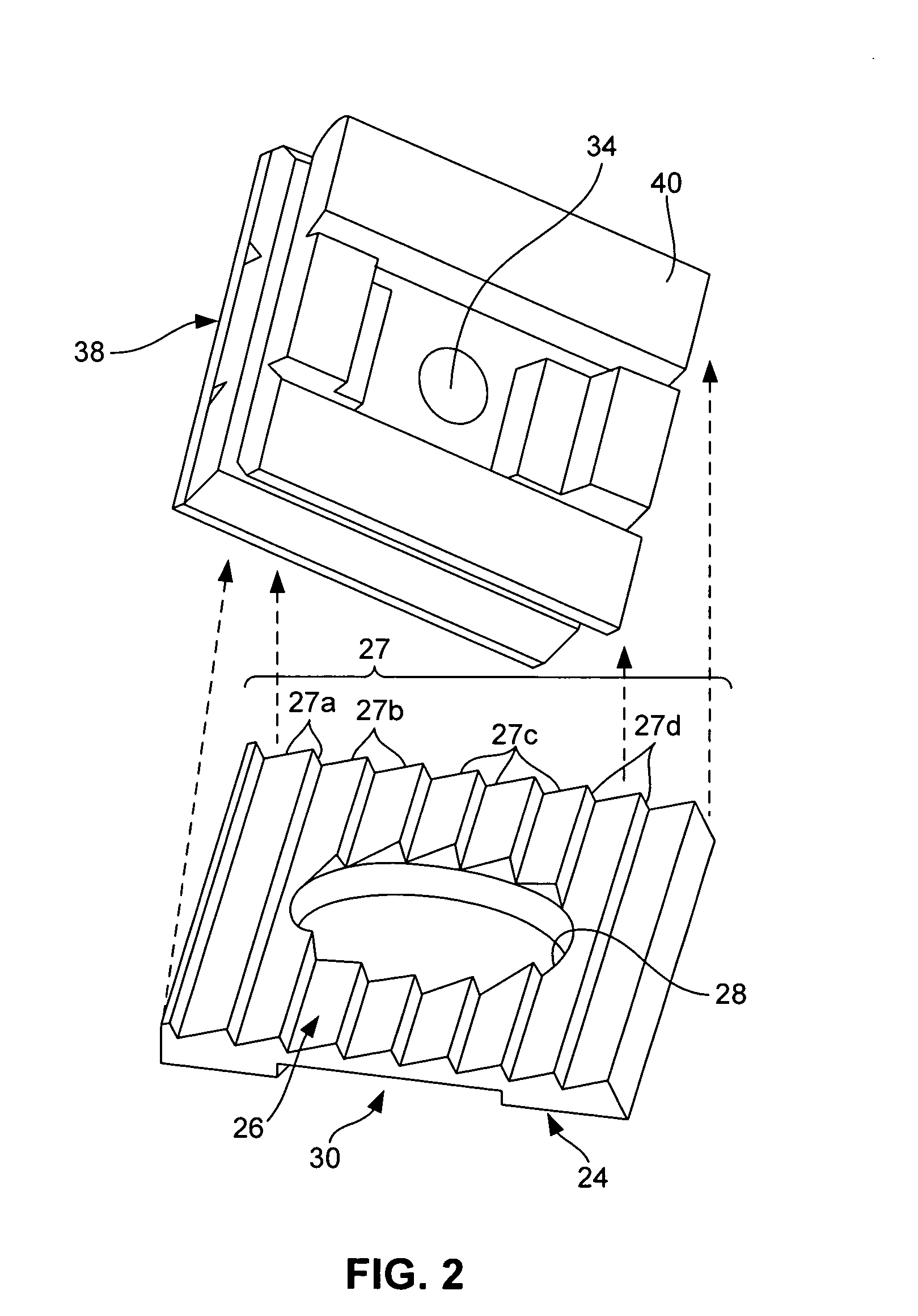
[0019] Referring to FIG. 2, an aperture plate 24 has a surface treated to absorb peripheral light or direct peripheral light away from a viewer's field of view. By directing the peripheral light away from the viewer's field of view, the plate 24 may eliminate or reduce the intensity of image artifacts, such as viewable bright spots. Treatments include providing a patterned surface.

[0020] With further reference to FIG. 2, the exemplary aperture plate 24 has formed on one face an angled surface structure 26, which surrounds a central aperture opening 28. A MEMS mirror 34 is contained within a housing 38, which has an open or transparent top 40 onto which the aperture plate 24 is mounted with the aperture opening 28 in optical alignment with the mirror 34 and the angled surface structure 26 facing away from the mirror toward a source beam of light as illustrated in FIG. 3. When so assembled, the plane of a face 30 (opposite structure 26) of the aperture plate 24 is substantially paral...


PUM


Abstract

An aperture plate includes an opening and a surface adjacent to the opening. The opening passes electromagnetic energy such as light to a reflector that is aligned with the opening and that directs the electromagnetic energy to a location. The surface reflects incident electromagnetic energy away from the location in a direction that is outside of the range of directions. Such an aperture plate insures that electromagnetic energy, e.g., light, strikes only the desired portions of the reflector, and that peripheral light that is outside of the aperture opening is reflected away from the location, e.g., display screen, toward which the reflector directs the electromagnetic energy. Furthermore, because such an aperture plate is mounted near the reflector, the alignment tolerances are typically less stringent than for an aperture plate mounted near the energy source.

Description

BACKGROUND OF THE INVENTION [0001] Scanned beam displays and image-capture devices have been developed to produce high-resolution images. As shown in FIG. 1, a modulated source 10 of light, which may include a modulated point source of light, is formed into a source beam 13 by optics, e.g., a focus lens 12, and directed by the lens onto a moving scan mirror 14, which reflects the beam onto an image curve or plane, such as a display screen 16, to create a viewable image. The mirror 14 may also scan the beam 13 directly into a viewer's eye (not shown in FIG. 1) to create the image directly on the viewer's retina. One application of this latter technique is for use in a head-worn personal display system, such as described in U.S. Pat. No. 5,467,104, entitled VIRTUAL RETINAL DISPLAY (VRD), which is incorporated by reference. Furthermore, the mirror 14 may be a bi-axial microelectromechanical scanner (MEMS) that scans the beam in a raster pattern. Such a MEMS is described, for example, i...

Claims


Application Information

Patent Timeline
IPC IPC(8): G02B26/08
CPCG02B5/005G02B26/0833
Inventor WATSON, MATHEW D.WIKLOF, CHRISTOPHER A.
Owner MICROVISION
Why Eureka
Try Eureka