
Method and system for testing a display panel assembly

a display panel and assembly technology, applied in the field of method and system for testing a display panel assembly, can solve the problems of reducing the display quality of the display device, affecting the yield and cost of the process, etc., and achieves the reduction of the time required for detecting defects, the effect of improving yield and reducing costs

Inactive Publication Date: 2006-06-08
SAMSUNG DISPLAY CO LTD
View PDF18 Cites 30 Cited by
  • Summary
  • Abstract
  • Description
  • Claims
  • Application Information

AI Technical Summary

Benefits of technology

[0035] According to the present invention, a visual inspection process may be performed automatically. Thus, defects in display devices may be rapidly detected. The time required for detecting the defects is minimized with improved yield and reduced costs. Furthermore, the defects may be accurately detected so that display quality of the display device may be increased.

Problems solved by technology

The labor-intensive and manual nature of the inspection process can affect yield and cost.
It is possible that the defects may not be accurately detected during a manual inspection process, decreasing display quality of the display device.

Method used


Image

  • Method and system for testing a display panel assembly
  • Method and system for testing a display panel assembly
  • Method and system for testing a display panel assembly

Examples


Embodiment Construction

[0047] Hereinafter, the exemplary embodiments of the present invention will be described in detail with reference to the accompanying drawings. In the drawings, the size and relative sizes of layers and regions may be exaggerated for clarity. It will be understood that when an element or layer is referred to as being “on” or “connected to” another element or layer, it can be directly on or directly connected to the other element or layer or intervening elements or layers may be present. Like reference numerals refer to similar or identical elements throughout the description of the figures.

[0048] It will be understood that, although the terms first, second, etc. may be used herein to describe various elements, components or layers, these elements, components or layers should not be limited by these terms. These terms are only used to distinguish one element, component or layer from another element, component or layer. Thus, a first element, component or layer could be termed a seco...


PUM


Abstract

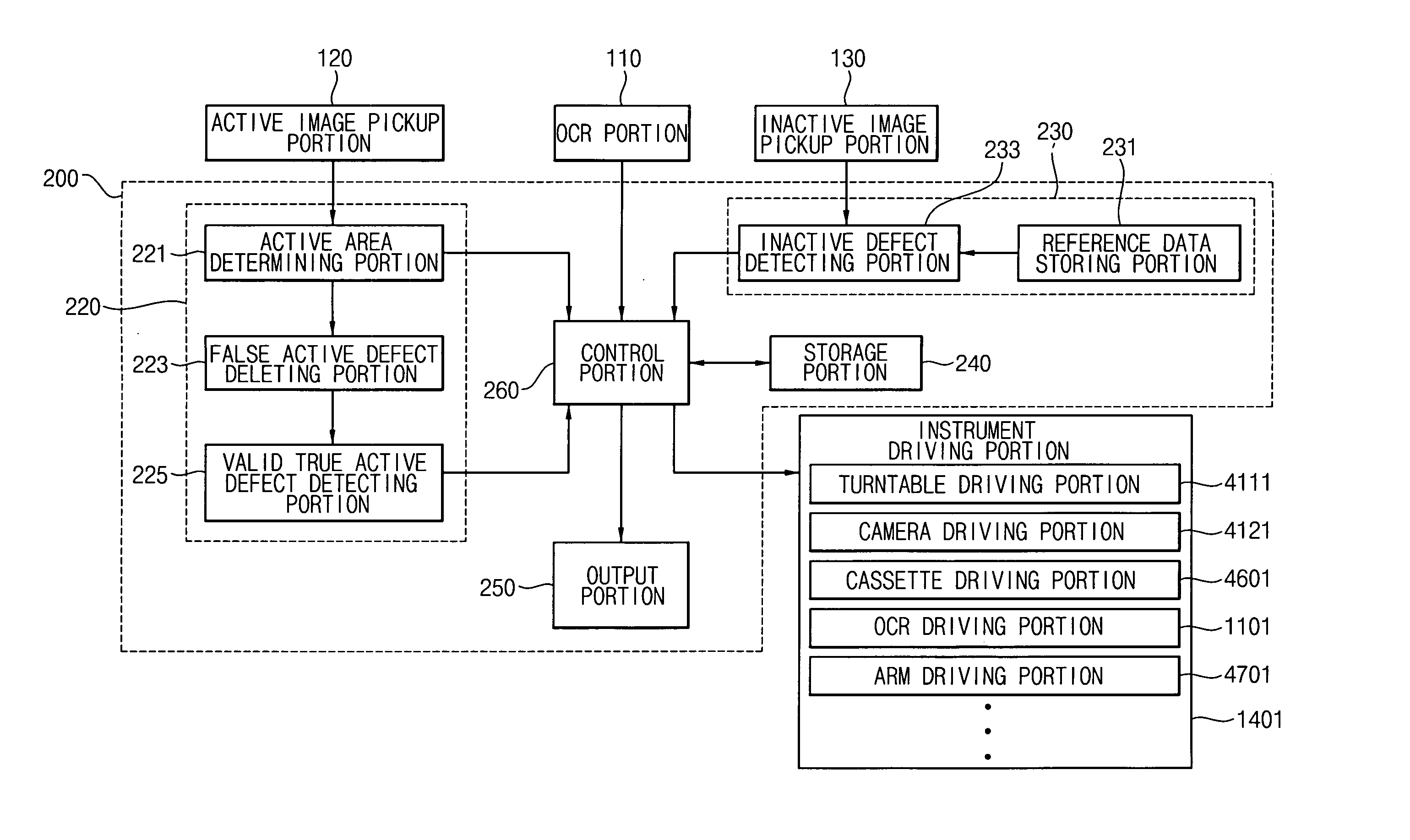
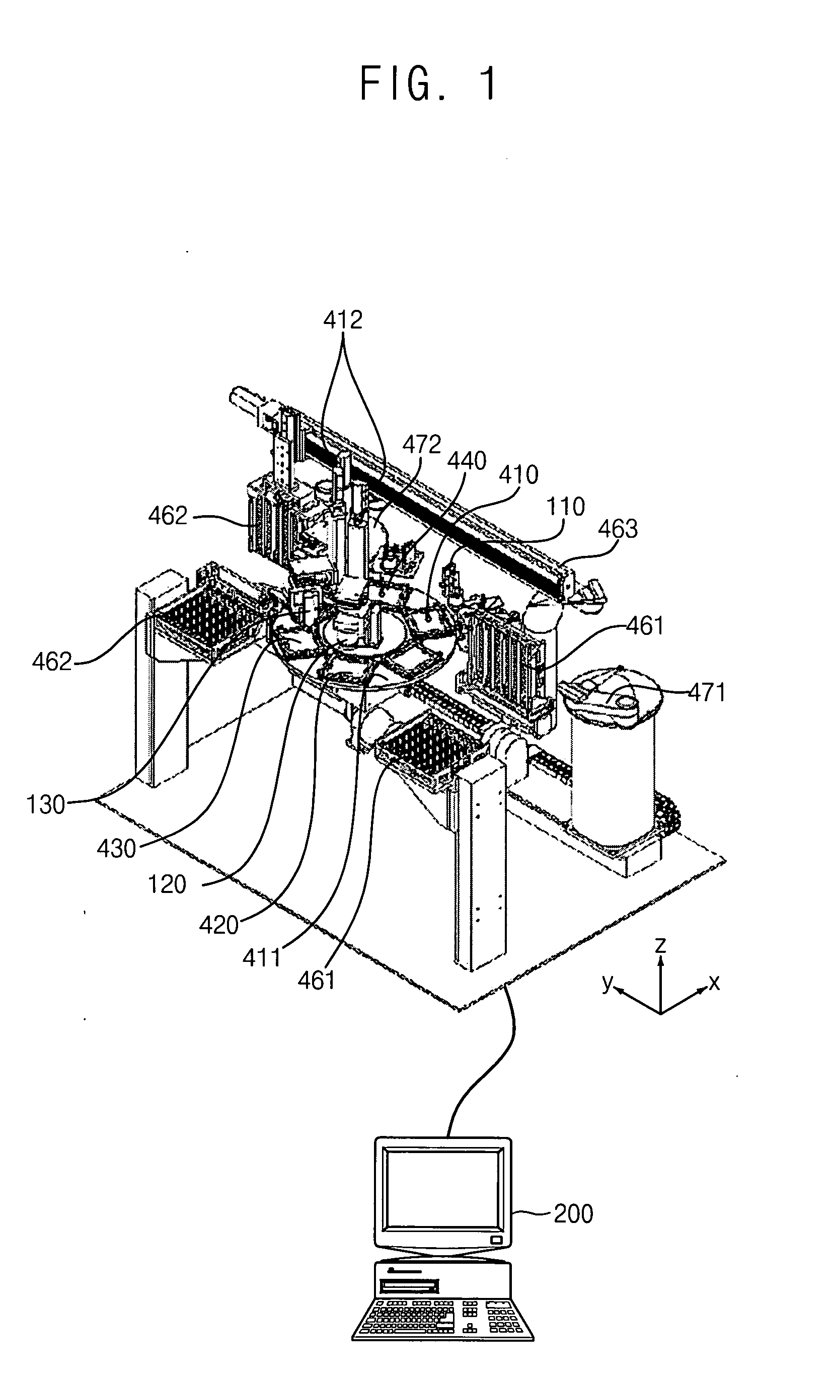
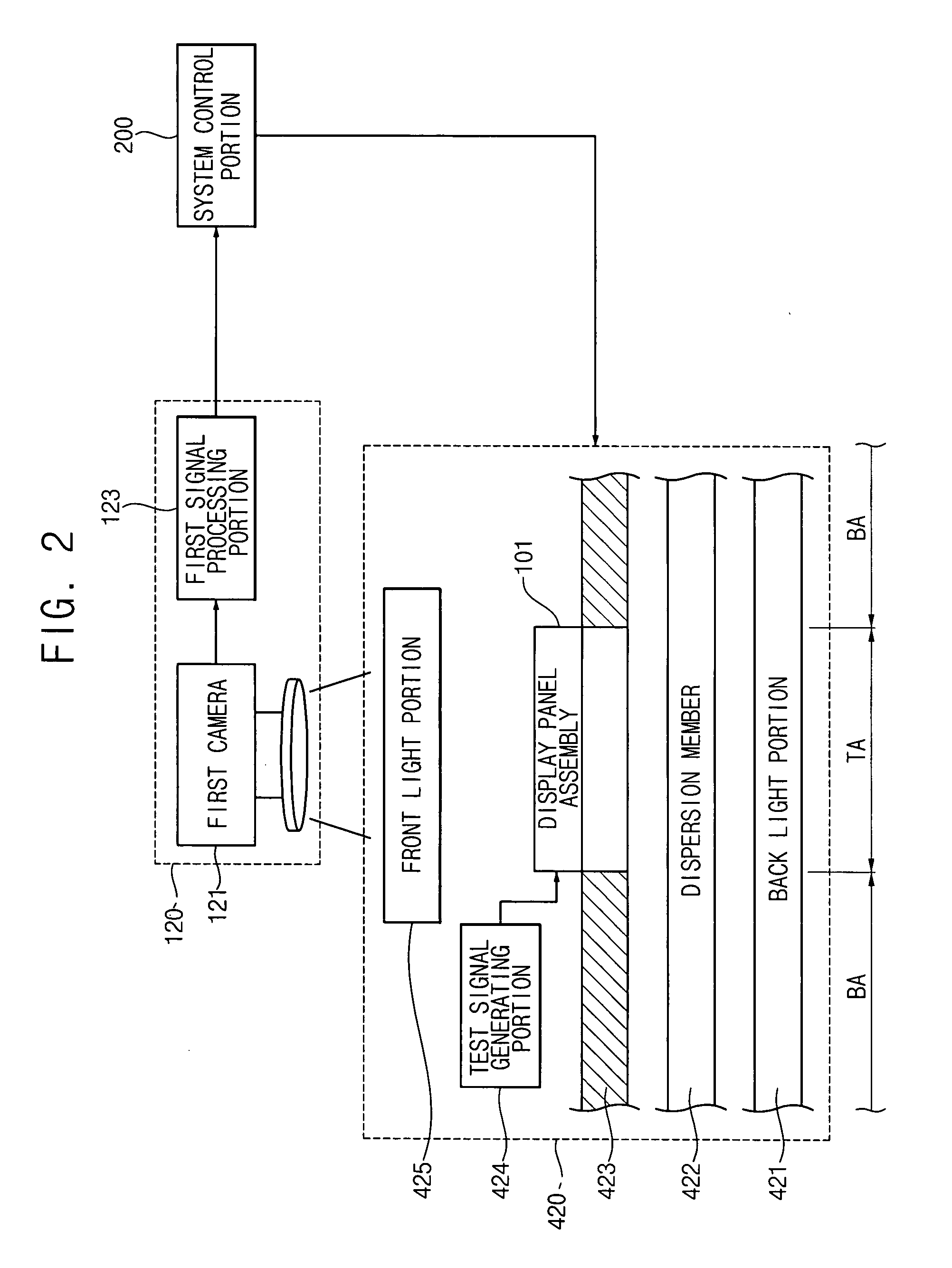
A test system includes a rotatable turntable, a loading section, a first image pickup section, a second image pickup section, a system control section and an unloading section. The loading section loads a display panel assembly onto the stage. The loading section recognizes a unique number of the display panel assembly. The first image pickup section obtains an active area image data from an active area image. A valid first active area defect is detected using an active area image data obtained from an active area image displayed on the display panel assembly. An inactive area defect is detected based on an inactive area image data and a reference inactive area image data.

Description

CROSS-REFERENCE TO RELATED APPLICATION [0001] This application claims priority to Korean Patent Application No. 2004-91809, filed on Nov. 11, 2004, the disclosure of which is herein incorporated by reference in its entirety. BACKGROUND OF THE INVENTION [0002] 1. Field of the Invention [0003] The present invention relates to a method and system for testing a display panel assembly. More particularly, the present invention relates to a test system for automatically performing a visual inspection process and a method of testing a display panel assembly using the test system. [0004] 2. Description of the Related Art [0005] In general, a liquid crystal display panel includes a lower substrate, an upper substrate and a liquid crystal layer. The liquid crystal layer is disposed between the lower substrate and the upper substrate. The lower substrate includes a pixel area and a peripheral area. A drive signal can be applied to the peripheral area. [0006] The pixel area includes a data line,...

Claims


Application Information

Patent Timeline
Patent Type & Authority Applications(United States)
IPC IPC(8): G06K9/00
CPCG09G3/006G01N2021/1765G02F1/1309
Inventor KWON, SANG-HYUKYANG, KYOUNG-HOPARK, SOON-JAE
Owner SAMSUNG DISPLAY CO LTD
Learn More